[CommandMethod("Polyline_2D_3D")] publicstaticvoidPolyline_2D_3D() { // Get the current document and database, and start a transaction Document acDoc = Application.DocumentManager.MdiActiveDocument; Database acCurDb = acDoc.Database;
using (Transaction acTrans = acCurDb.TransactionManager.StartTransaction()) { // Open the Block table record for read BlockTable acBlkTbl; acBlkTbl = acTrans.GetObject(acCurDb.BlockTableId, OpenMode.ForRead) as BlockTable;
// Open the Block table record Model space for write BlockTableRecord acBlkTblRec; acBlkTblRec = acTrans.GetObject(acBlkTbl[BlockTableRecord.ModelSpace], OpenMode.ForWrite) as BlockTableRecord;
// Create a polyline with two segments (3 points) using (Polyline acPoly = new Polyline()) { acPoly.AddVertexAt(0, new Point2d(1, 1), 0, 0, 0); acPoly.AddVertexAt(1, new Point2d(1, 2), 0, 0, 0); acPoly.AddVertexAt(2, new Point2d(2, 2), 0, 0, 0); acPoly.ColorIndex = 1;
// Add the new object to the block table record and the transaction acBlkTblRec.AppendEntity(acPoly); acTrans.AddNewlyCreatedDBObject(acPoly, true);
// Create a 3D polyline with two segments (3 points) using (Polyline3d acPoly3d = new Polyline3d()) { acPoly3d.ColorIndex = 5;
// Add the new object to the block table record and the transaction acBlkTblRec.AppendEntity(acPoly3d); acTrans.AddNewlyCreatedDBObject(acPoly3d, true);
// Before adding vertexes, the polyline must be in the drawing Point3dCollection acPts3dPoly = new Point3dCollection(); acPts3dPoly.Add(new Point3d(1, 1, 0)); acPts3dPoly.Add(new Point3d(2, 1, 0)); acPts3dPoly.Add(new Point3d(2, 2, 0));
foreach (Point3d acPt3d in acPts3dPoly) { using (PolylineVertex3d acPolVer3d = new PolylineVertex3d(acPt3d)) { acPoly3d.AppendVertex(acPolVer3d); acTrans.AddNewlyCreatedDBObject(acPolVer3d, true); } }
// Get the coordinates of the lightweight polyline Point2dCollection acPts2d = new Point2dCollection(); for (int nCnt = 0; nCnt < acPoly.NumberOfVertices; nCnt++) { acPts2d.Add(acPoly.GetPoint2dAt(nCnt)); }
// Get the coordinates of the 3D polyline Point3dCollection acPts3d = new Point3dCollection(); foreach (ObjectId acObjIdVert in acPoly3d) { PolylineVertex3d acPolVer3d; acPolVer3d = acTrans.GetObject(acObjIdVert, OpenMode.ForRead) as PolylineVertex3d;
[CommandMethod("NewUCS")] publicstaticvoidNewUCS() { // Get the current document and database, and start a transaction Document acDoc = Application.DocumentManager.MdiActiveDocument; Database acCurDb = acDoc.Database;
using (Transaction acTrans = acCurDb.TransactionManager.StartTransaction()) { // Open the UCS table for read UcsTable acUCSTbl; acUCSTbl = acTrans.GetObject(acCurDb.UcsTableId, OpenMode.ForRead) as UcsTable;
UcsTableRecord acUCSTblRec;
// Check to see if the "New_UCS" UCS table record exists if (acUCSTbl.Has("New_UCS") == false) { acUCSTblRec = new UcsTableRecord(); acUCSTblRec.Name = "New_UCS";
// Open the UCSTable for write acTrans.GetObject(acCurDb.UcsTableId, OpenMode.ForWrite);
// Add the new UCS table record acUCSTbl.Add(acUCSTblRec); acTrans.AddNewlyCreatedDBObject(acUCSTblRec, true); } else { acUCSTblRec = acTrans.GetObject(acUCSTbl["New_UCS"], OpenMode.ForWrite) as UcsTableRecord; }
acUCSTblRec.Origin = new Point3d(4, 5, 3); acUCSTblRec.XAxis = new Vector3d(1, 0, 0); acUCSTblRec.YAxis = new Vector3d(0, 1, 0);
// Open the active viewport ViewportTableRecord acVportTblRec; acVportTblRec = acTrans.GetObject(acDoc.Editor.ActiveViewportId, OpenMode.ForWrite) as ViewportTableRecord;
// Display the UCS Icon at the origin of the current viewport acVportTblRec.IconAtOrigin = true; acVportTblRec.IconEnabled = true;
// Set the UCS current acVportTblRec.SetUcs(acUCSTblRec.ObjectId); acDoc.Editor.UpdateTiledViewportsFromDatabase();
// Display the name of the current UCS UcsTableRecord acUCSTblRecActive; acUCSTblRecActive = acTrans.GetObject(acVportTblRec.UcsName, OpenMode.ForRead) as UcsTableRecord;
Application.ShowAlertDialog("The current UCS is: " + acUCSTblRecActive.Name);
PromptPointResult pPtRes; PromptPointOptions pPtOpts = new PromptPointOptions("");
// Prompt for a point pPtOpts.Message = "\nEnter a point: "; pPtRes = acDoc.Editor.GetPoint(pPtOpts);
Point3d pPt3dWCS; Point3d pPt3dUCS;
// If a point was entered, then translate it to the current UCS if (pPtRes.Status == PromptStatus.OK) { pPt3dWCS = pPtRes.Value; pPt3dUCS = pPtRes.Value;
// Translate the point from the current UCS to the WCS Matrix3d newMatrix = new Matrix3d(); newMatrix = Matrix3d.AlignCoordinateSystem(Point3d.Origin, Vector3d.XAxis, Vector3d.YAxis, Vector3d.ZAxis, acVportTblRec.Ucs.Origin, acVportTblRec.Ucs.Xaxis, acVportTblRec.Ucs.Yaxis, acVportTblRec.Ucs.Zaxis);
[CommandMethod("TranslateCoordinates")] publicstaticvoidTranslateCoordinates() { // Get the current document and database, and start a transaction Document acDoc = Application.DocumentManager.MdiActiveDocument; Database acCurDb = acDoc.Database;
using (Transaction acTrans = acCurDb.TransactionManager.StartTransaction()) { // Open the Block table record for read BlockTable acBlkTbl; acBlkTbl = acTrans.GetObject(acCurDb.BlockTableId, OpenMode.ForRead) as BlockTable;
// Open the Block table record Model space for write BlockTableRecord acBlkTblRec; acBlkTblRec = acTrans.GetObject(acBlkTbl[BlockTableRecord.ModelSpace], OpenMode.ForWrite) as BlockTableRecord;
// Create a 2D polyline with two segments (3 points) using (Polyline2d acPoly2d = new Polyline2d()) { // Add the new object to the block table record and the transaction acBlkTblRec.AppendEntity(acPoly2d); acTrans.AddNewlyCreatedDBObject(acPoly2d, true);
// Before adding vertexes, the polyline must be in the drawing Point3dCollection acPts2dPoly = new Point3dCollection(); acPts2dPoly.Add(new Point3d(1, 1, 0)); acPts2dPoly.Add(new Point3d(1, 2, 0)); acPts2dPoly.Add(new Point3d(2, 2, 0)); acPts2dPoly.Add(new Point3d(3, 2, 0)); acPts2dPoly.Add(new Point3d(4, 4, 0));
foreach (Point3d acPt3d in acPts2dPoly) { Vertex2d acVer2d = new Vertex2d(acPt3d, 0, 0, 0, 0); acPoly2d.AppendVertex(acVer2d); acTrans.AddNewlyCreatedDBObject(acVer2d, true); }
// Set the normal of the 2D polyline acPoly2d.Normal = new Vector3d(0, 1, 2);
// Get the first coordinate of the 2D polyline Point3dCollection acPts3d = new Point3dCollection(); Vertex2d acFirstVer = null;
foreach (ObjectId acObjIdVert in acPoly2d) { acFirstVer = acTrans.GetObject(acObjIdVert, OpenMode.ForRead) as Vertex2d;
acPts3d.Add(acFirstVer.Position);
break; }
// Get the first point of the polyline and // use the eleveation for the Z value Point3d pFirstVer = new Point3d(acFirstVer.Position.X, acFirstVer.Position.Y, acPoly2d.Elevation);
// Translate the OCS to WCS Matrix3d mWPlane = Matrix3d.WorldToPlane(acPoly2d.Normal); Point3d pWCSPt = pFirstVer.TransformBy(mWPlane);
Application.ShowAlertDialog("The first vertex has the following " + "coordinates:" + "\nOCS: " + pFirstVer.ToString() + "\nWCS: " + pWCSPt.ToString()); }
// Save the new objects to the database acTrans.Commit(); } }
[CommandMethod("Create3DMesh")] publicstaticvoidCreate3DMesh() { // Get the current document and database, and start a transaction Document acDoc = Application.DocumentManager.MdiActiveDocument; Database acCurDb = acDoc.Database;
using (Transaction acTrans = acCurDb.TransactionManager.StartTransaction()) { // Open the Block table record for read BlockTable acBlkTbl; acBlkTbl = acTrans.GetObject(acCurDb.BlockTableId, OpenMode.ForRead) as BlockTable;
// Open the Block table record Model space for write BlockTableRecord acBlkTblRec; acBlkTblRec = acTrans.GetObject(acBlkTbl[BlockTableRecord.ModelSpace], OpenMode.ForWrite) as BlockTableRecord;
// Create a polygon mesh using (PolygonMesh acPolyMesh = new PolygonMesh()) { acPolyMesh.MSize = 4; acPolyMesh.NSize = 4;
// Add the new object to the block table record and the transaction acBlkTblRec.AppendEntity(acPolyMesh); acTrans.AddNewlyCreatedDBObject(acPolyMesh, true);
// Before adding vertexes, the polyline must be in the drawing Point3dCollection acPts3dPMesh = new Point3dCollection(); acPts3dPMesh.Add(new Point3d(0, 0, 0)); acPts3dPMesh.Add(new Point3d(2, 0, 1)); acPts3dPMesh.Add(new Point3d(4, 0, 0)); acPts3dPMesh.Add(new Point3d(6, 0, 1));
foreach (Point3d acPt3d in acPts3dPMesh) { PolygonMeshVertex acPMeshVer = new PolygonMeshVertex(acPt3d); acPolyMesh.AppendVertex(acPMeshVer); acTrans.AddNewlyCreatedDBObject(acPMeshVer, true); } }
// Open the active viewport ViewportTableRecord acVportTblRec; acVportTblRec = acTrans.GetObject(acDoc.Editor.ActiveViewportId, OpenMode.ForWrite) as ViewportTableRecord;
// Rotate the view direction of the current viewport acVportTblRec.ViewDirection = new Vector3d(-1, -1, 1); acDoc.Editor.UpdateTiledViewportsFromDatabase();
// Save the new objects to the database acTrans.Commit(); } }
[CommandMethod("CreatePolyfaceMesh")] publicstaticvoidCreatePolyfaceMesh() { // Get the current document and database, and start a transaction Document acDoc = Application.DocumentManager.MdiActiveDocument; Database acCurDb = acDoc.Database;
using (Transaction acTrans = acCurDb.TransactionManager.StartTransaction()) { // Open the Block table record for read BlockTable acBlkTbl; acBlkTbl = acTrans.GetObject(acCurDb.BlockTableId, OpenMode.ForRead) as BlockTable;
// Open the Block table record Model space for write BlockTableRecord acBlkTblRec; acBlkTblRec = acTrans.GetObject(acBlkTbl[BlockTableRecord.ModelSpace], OpenMode.ForWrite) as BlockTableRecord;
// Create a polyface mesh using (PolyFaceMesh acPFaceMesh = new PolyFaceMesh()) { // Add the new object to the block table record and the transaction acBlkTblRec.AppendEntity(acPFaceMesh); acTrans.AddNewlyCreatedDBObject(acPFaceMesh, true);
// Before adding vertexes, the polyline must be in the drawing Point3dCollection acPts3dPFMesh = new Point3dCollection(); acPts3dPFMesh.Add(new Point3d(4, 7, 0)); acPts3dPFMesh.Add(new Point3d(5, 7, 0)); acPts3dPFMesh.Add(new Point3d(6, 7, 0));
foreach (Point3d acPt3d in acPts3dPFMesh) { PolyFaceMeshVertex acPMeshVer = new PolyFaceMeshVertex(acPt3d); acPFaceMesh.AppendVertex(acPMeshVer); acTrans.AddNewlyCreatedDBObject(acPMeshVer, true); }
using (FaceRecord acFaceRec1 = new FaceRecord(1, 2, 5, 4)) { acPFaceMesh.AppendFaceRecord(acFaceRec1); acTrans.AddNewlyCreatedDBObject(acFaceRec1, true); }
using (FaceRecord acFaceRec2 = new FaceRecord(2, 3, 6, 5)) { acPFaceMesh.AppendFaceRecord(acFaceRec2); acTrans.AddNewlyCreatedDBObject(acFaceRec2, true); } }
// Open the active viewport ViewportTableRecord acVportTblRec; acVportTblRec = acTrans.GetObject(acDoc.Editor.ActiveViewportId, OpenMode.ForWrite) as ViewportTableRecord;
// Rotate the view direction of the current viewport acVportTblRec.ViewDirection = new Vector3d(-1, -1, 1); acDoc.Editor.UpdateTiledViewportsFromDatabase();
// Save the new objects to the database acTrans.Commit(); } }
[CommandMethod("CreateWedge")] publicstaticvoidCreateWedge() { // Get the current document and database, and start a transaction Document acDoc = Application.DocumentManager.MdiActiveDocument; Database acCurDb = acDoc.Database;
using (Transaction acTrans = acCurDb.TransactionManager.StartTransaction()) { // Open the Block table record for read BlockTable acBlkTbl; acBlkTbl = acTrans.GetObject(acCurDb.BlockTableId, OpenMode.ForRead) as BlockTable;
// Open the Block table record Model space for write BlockTableRecord acBlkTblRec; acBlkTblRec = acTrans.GetObject(acBlkTbl[BlockTableRecord.ModelSpace], OpenMode.ForWrite) as BlockTableRecord;
// Create a 3D solid wedge using (Solid3d acSol3D = new Solid3d()) { acSol3D.CreateWedge(10, 15, 20);
// Position the center of the 3D solid at (5,5,0) acSol3D.TransformBy(Matrix3d.Displacement(new Point3d(5, 5, 0) - Point3d.Origin));
// Add the new object to the block table record and the transaction acBlkTblRec.AppendEntity(acSol3D); acTrans.AddNewlyCreatedDBObject(acSol3D, true); }
// Open the active viewport ViewportTableRecord acVportTblRec; acVportTblRec = acTrans.GetObject(acDoc.Editor.ActiveViewportId, OpenMode.ForWrite) as ViewportTableRecord;
// Rotate the view direction of the current viewport acVportTblRec.ViewDirection = new Vector3d(-1, -1, 1); acDoc.Editor.UpdateTiledViewportsFromDatabase();
// Save the new objects to the database acTrans.Commit(); } }
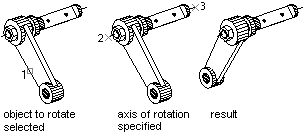
[CommandMethod("Rotate_3DBox")] publicstaticvoidRotate_3DBox() { // Get the current document and database, and start a transaction Document acDoc = Application.DocumentManager.MdiActiveDocument; Database acCurDb = acDoc.Database;
using (Transaction acTrans = acCurDb.TransactionManager.StartTransaction()) { // Open the Block table for read BlockTable acBlkTbl; acBlkTbl = acTrans.GetObject(acCurDb.BlockTableId, OpenMode.ForRead) as BlockTable;
// Open the Block table record Model space for write BlockTableRecord acBlkTblRec; acBlkTblRec = acTrans.GetObject(acBlkTbl[BlockTableRecord.ModelSpace], OpenMode.ForWrite) as BlockTableRecord;
// Create a 3D solid box using (Solid3d acSol3D = new Solid3d()) { acSol3D.CreateBox(5, 7, 10);
// Position the center of the 3D solid at (5,5,0) acSol3D.TransformBy(Matrix3d.Displacement(new Point3d(5, 5, 0) - Point3d.Origin));
// Rotate the 3D solid 30 degrees around the axis that is // defined by the points (-3,4,0) and (-3,-4,0) Vector3d vRot = new Point3d(-3, 4, 0). GetVectorTo(new Point3d(-3, -4, 0));
acSol3D.TransformBy(Matrix3d.Rotation(0.5236, vRot, new Point3d(-3, 4, 0)));
// Add the new object to the block table record and the transaction acBlkTblRec.AppendEntity(acSol3D); acTrans.AddNewlyCreatedDBObject(acSol3D, true); }
// Save the new objects to the database acTrans.Commit(); } }
static Point2d PolarPoints(Point2d pPt, double dAng, double dDist) { returnnew Point2d(pPt.X + dDist * Math.Cos(dAng), pPt.Y + dDist * Math.Sin(dAng)); } [CommandMethod("CreateRectangular3DArray")] publicstaticvoidCreateRectangular3DArray() { // Get the current document and database, and start a transaction Document acDoc = Application.DocumentManager.MdiActiveDocument; Database acCurDb = acDoc.Database;
using (Transaction acTrans = acCurDb.TransactionManager.StartTransaction()) { // Open the Block table record for read BlockTable acBlkTbl; acBlkTbl = acTrans.GetObject(acCurDb.BlockTableId, OpenMode.ForRead) as BlockTable;
// Open the Block table record Model space for write BlockTableRecord acBlkTblRec; acBlkTblRec = acTrans.GetObject(acBlkTbl[BlockTableRecord.ModelSpace], OpenMode.ForWrite) as BlockTableRecord;
// Create a circle that is at 2,2 with a radius of 0.5 using (Circle acCirc = new Circle()) { acCirc.Center = new Point3d(2, 2, 0); acCirc.Radius = 0.5;
// Add the new object to the block table record and the transaction acBlkTblRec.AppendEntity(acCirc); acTrans.AddNewlyCreatedDBObject(acCirc, true);
// Create a rectangular array with 4 rows, 4 columns, and 3 levels int nRows = 4; int nColumns = 4; int nLevels = 3;
// Set the row, column, and level offsets along with the base array angle double dRowOffset = 1; double dColumnOffset = 1; double dLevelsOffset = 4; double dArrayAng = 0;
// Get the angle from X for the current UCS Matrix3d curUCSMatrix = acDoc.Editor.CurrentUserCoordinateSystem; CoordinateSystem3d curUCS = curUCSMatrix.CoordinateSystem3d; Vector2d acVec2dAng = new Vector2d(curUCS.Xaxis.X, curUCS.Xaxis.Y);
// If the UCS is rotated, adjust the array angle accordingly dArrayAng = dArrayAng + acVec2dAng.Angle;
// Use the upper-left corner of the objects extents for the array base point Extents3d acExts = acCirc.Bounds.GetValueOrDefault(); Point2d acPt2dArrayBase = new Point2d(acExts.MinPoint.X, acExts.MaxPoint.Y);
// Track the objects created for each column DBObjectCollection acDBObjCollCols = new DBObjectCollection(); acDBObjCollCols.Add(acCirc);
// Create the number of objects for the first column int nColumnsCount = 1; while (nColumns > nColumnsCount) { Entity acEntClone = acCirc.Clone() as Entity; acDBObjCollCols.Add(acEntClone);
// Caclucate the new point for the copied object (move) Point2d acPt2dTo = PolarPoints(acPt2dArrayBase, dArrayAng, dColumnOffset * nColumnsCount);
[CommandMethod("MirrorABox3D")] publicstaticvoidMirrorABox3D() { // Get the current document and database, and start a transaction Document acDoc = Application.DocumentManager.MdiActiveDocument; Database acCurDb = acDoc.Database;
using (Transaction acTrans = acCurDb.TransactionManager.StartTransaction()) { // Open the Block table record for read BlockTable acBlkTbl; acBlkTbl = acTrans.GetObject(acCurDb.BlockTableId, OpenMode.ForRead) as BlockTable;
// Open the Block table record Model space for write BlockTableRecord acBlkTblRec; acBlkTblRec = acTrans.GetObject(acBlkTbl[BlockTableRecord.ModelSpace], OpenMode.ForWrite) as BlockTableRecord;
// Create a 3D solid box using (Solid3d acSol3D = new Solid3d()) { acSol3D.CreateBox(5, 7, 10);
// Position the center of the 3D solid at (5,5,0) acSol3D.TransformBy(Matrix3d.Displacement(new Point3d(5, 5, 0) - Point3d.Origin));
// Add the new object to the block table record and the transaction acBlkTblRec.AppendEntity(acSol3D); acTrans.AddNewlyCreatedDBObject(acSol3D, true);
// Create a copy of the original 3D solid and change the color of the copy Solid3d acSol3DCopy = acSol3D.Clone() as Solid3d; acSol3DCopy.ColorIndex = 1;
// Define the mirror plane Plane acPlane = new Plane(new Point3d(1.25, 0, 0), new Point3d(1.25, 2, 0), new Point3d(1.25, 2, 2));
// Mirror the 3D solid across the plane acSol3DCopy.TransformBy(Matrix3d.Mirroring(acPlane));
// Add the new object to the block table record and the transaction acBlkTblRec.AppendEntity(acSol3DCopy); acTrans.AddNewlyCreatedDBObject(acSol3DCopy, true); }
// Save the new objects to the database acTrans.Commit(); } }
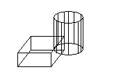
[CommandMethod("FindInterferenceBetweenSolids")] publicstaticvoidFindInterferenceBetweenSolids() { // Get the current document and database, and start a transaction Document acDoc = Application.DocumentManager.MdiActiveDocument; Database acCurDb = acDoc.Database;
using (Transaction acTrans = acCurDb.TransactionManager.StartTransaction()) { // Open the Block table record for read BlockTable acBlkTbl; acBlkTbl = acTrans.GetObject(acCurDb.BlockTableId, OpenMode.ForRead) as BlockTable;
// Open the Block table record Model space for write BlockTableRecord acBlkTblRec; acBlkTblRec = acTrans.GetObject(acBlkTbl[BlockTableRecord.ModelSpace], OpenMode.ForWrite) as BlockTableRecord;
// Create a 3D solid box using (Solid3d acSol3DBox = new Solid3d()) { acSol3DBox.CreateBox(5, 7, 10); acSol3DBox.ColorIndex = 7;
// Position the center of the 3D solid at (5,5,0) acSol3DBox.TransformBy(Matrix3d.Displacement(new Point3d(5, 5, 0) - Point3d.Origin));
// Add the new object to the block table record and the transaction acBlkTblRec.AppendEntity(acSol3DBox); acTrans.AddNewlyCreatedDBObject(acSol3DBox, true);
// Create a 3D solid cylinder // 3D solids are created at (0,0,0) so there is no need to move it using (Solid3d acSol3DCyl = new Solid3d()) { acSol3DCyl.CreateFrustum(20, 5, 5, 5); acSol3DCyl.ColorIndex = 4;
// Add the new object to the block table record and the transaction acBlkTblRec.AppendEntity(acSol3DCyl); acTrans.AddNewlyCreatedDBObject(acSol3DCyl, true);
// Create a 3D solid from the interference of the box and cylinder Solid3d acSol3DCopy = acSol3DCyl.Clone() as Solid3d;
// Check to see if the 3D solids overlap if (acSol3DCopy.CheckInterference(acSol3DBox) == true) { acSol3DCopy.BooleanOperation(BooleanOperationType.BoolIntersect, acSol3DBox.Clone() as Solid3d);
acSol3DCopy.ColorIndex = 1; }
// Add the new object to the block table record and the transaction acBlkTblRec.AppendEntity(acSol3DCopy); acTrans.AddNewlyCreatedDBObject(acSol3DCopy, true); } }
// Save the new objects to the database acTrans.Commit(); } }
[CommandMethod("SliceABox")] publicstaticvoidSliceABox() { // Get the current document and database, and start a transaction Document acDoc = Application.DocumentManager.MdiActiveDocument; Database acCurDb = acDoc.Database;
using (Transaction acTrans = acCurDb.TransactionManager.StartTransaction()) { // Open the Block table record for read BlockTable acBlkTbl; acBlkTbl = acTrans.GetObject(acCurDb.BlockTableId, OpenMode.ForRead) as BlockTable;
// Open the Block table record Model space for write BlockTableRecord acBlkTblRec; acBlkTblRec = acTrans.GetObject(acBlkTbl[BlockTableRecord.ModelSpace], OpenMode.ForWrite) as BlockTableRecord;
// Create a 3D solid box using (Solid3d acSol3D = new Solid3d()) { acSol3D.CreateBox(5, 7, 10); acSol3D.ColorIndex = 7;
// Position the center of the 3D solid at (5,5,0) acSol3D.TransformBy(Matrix3d.Displacement(new Point3d(5, 5, 0) - Point3d.Origin));
// Add the new object to the block table record and the transaction acBlkTblRec.AppendEntity(acSol3D); acTrans.AddNewlyCreatedDBObject(acSol3D, true);
// Define the mirror plane Plane acPlane = new Plane(new Point3d(1.5, 7.5, 0), new Point3d(1.5, 7.5, 10), new Point3d(8.5, 2.5, 10));
// Add the new object to the block table record and the transaction acBlkTblRec.AppendEntity(acSol3DSlice); acTrans.AddNewlyCreatedDBObject(acSol3DSlice, true); }
// Save the new objects to the database acTrans.Commit(); } }