// Open the Registered Application table for read
RegAppTable acRegAppTbl;
acRegAppTbl = <transaction>.GetObject(<current_database>.RegAppTableId,
                                      OpenMode.ForRead) as RegAppTable;

// Check to see if the app "ACAD_DSTYLE_DIMJAG_POSITION" is
// registered and if not add it to the RegApp table
if (acRegAppTbl.Has("ACAD_DSTYLE_DIMJAG_POSITION") == false)
{
    using (RegAppTableRecord acRegAppTblRec = new RegAppTableRecord())
    {
        acRegAppTblRec.Name = "ACAD_DSTYLE_DIMJAG_POSITION";

        <transaction>.GetObject(<current_database>.RegAppTableId, OpenMode.ForWrite);

        acRegAppTbl.Add(acRegAppTblRec);
        <transaction>.AddNewlyCreatedDBObject(acRegAppTblRec, true);
    }
}

// Create a result buffer to define the Xdata
ResultBuffer acResBuf = new ResultBuffer();
acResBuf.Add(new TypedValue((int)DxfCode.ExtendedDataRegAppName,
                                         "ACAD_DSTYLE_DIMJAG_POSITION"));
acResBuf.Add(new TypedValue((int)DxfCode.ExtendedDataInteger16, 387));
acResBuf.Add(new TypedValue((int)DxfCode.ExtendedDataInteger16, 3));
acResBuf.Add(new TypedValue((int)DxfCode.ExtendedDataInteger16, 389));
acResBuf.Add(new TypedValue((int)DxfCode.ExtendedDataXCoordinate,
                                         new Point3d(-1.26985, 3.91514, 0)));

// Attach the Xdata to the dimension
<dimension_object>.XData = acResBuf;
[CommandMethod("CreateRotatedDimension")] publicstaticvoidCreateRotatedDimension() { // Get the current database Document acDoc = Application.DocumentManager.MdiActiveDocument; Database acCurDb = acDoc.Database;
// Start a transaction using (Transaction acTrans = acCurDb.TransactionManager.StartTransaction()) { // Open the Block table for read BlockTable acBlkTbl; acBlkTbl = acTrans.GetObject(acCurDb.BlockTableId, OpenMode.ForRead) as BlockTable;
// Open the Block table record Model space for write BlockTableRecord acBlkTblRec; acBlkTblRec = acTrans.GetObject(acBlkTbl[BlockTableRecord.ModelSpace], OpenMode.ForWrite) as BlockTableRecord;
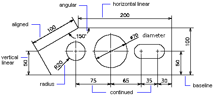
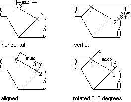
// Create the rotated dimension using (RotatedDimension acRotDim = new RotatedDimension()) { acRotDim.XLine1Point = new Point3d(0, 0, 0); acRotDim.XLine2Point = new Point3d(6, 3, 0); acRotDim.Rotation = 0.707; acRotDim.DimLinePoint = new Point3d(0, 5, 0); acRotDim.DimensionStyle = acCurDb.Dimstyle;
// Add the new object to Model space and the transaction acBlkTblRec.AppendEntity(acRotDim); acTrans.AddNewlyCreatedDBObject(acRotDim, true); }
// Commit the changes and dispose of the transaction acTrans.Commit(); } }
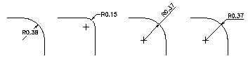
[CommandMethod("CreateRadialDimension")] publicstaticvoidCreateRadialDimension() { // Get the current database Document acDoc = Application.DocumentManager.MdiActiveDocument; Database acCurDb = acDoc.Database;
// Start a transaction using (Transaction acTrans = acCurDb.TransactionManager.StartTransaction()) { // Open the Block table for read BlockTable acBlkTbl; acBlkTbl = acTrans.GetObject(acCurDb.BlockTableId, OpenMode.ForRead) as BlockTable;
// Open the Block table record Model space for write BlockTableRecord acBlkTblRec; acBlkTblRec = acTrans.GetObject(acBlkTbl[BlockTableRecord.ModelSpace], OpenMode.ForWrite) as BlockTableRecord;
// Create the radial dimension using (RadialDimension acRadDim = new RadialDimension()) { acRadDim.Center = new Point3d(0, 0, 0); acRadDim.ChordPoint = new Point3d(5, 5, 0); acRadDim.LeaderLength = 5; acRadDim.DimensionStyle = acCurDb.Dimstyle;
// Add the new object to Model space and the transaction acBlkTblRec.AppendEntity(acRadDim); acTrans.AddNewlyCreatedDBObject(acRadDim, true); }
// Commit the changes and dispose of the transaction acTrans.Commit(); } }
[CommandMethod("CreateAngularDimension")] publicstaticvoidCreateAngularDimension() { // Get the current database Document acDoc = Application.DocumentManager.MdiActiveDocument; Database acCurDb = acDoc.Database;
// Start a transaction using (Transaction acTrans = acCurDb.TransactionManager.StartTransaction()) { // Open the Block table for read BlockTable acBlkTbl; acBlkTbl = acTrans.GetObject(acCurDb.BlockTableId, OpenMode.ForRead) as BlockTable;
// Open the Block table record Model space for write BlockTableRecord acBlkTblRec; acBlkTblRec = acTrans.GetObject(acBlkTbl[BlockTableRecord.ModelSpace], OpenMode.ForWrite) as BlockTableRecord;
// Create an angular dimension using (LineAngularDimension2 acLinAngDim = new LineAngularDimension2()) { acLinAngDim.XLine1Start = new Point3d(0, 5, 0); acLinAngDim.XLine1End = new Point3d(1, 7, 0); acLinAngDim.XLine2Start = new Point3d(0, 5, 0); acLinAngDim.XLine2End = new Point3d(1, 3, 0); acLinAngDim.ArcPoint = new Point3d(3, 5, 0); acLinAngDim.DimensionStyle = acCurDb.Dimstyle;
// Add the new object to Model space and the transaction acBlkTblRec.AppendEntity(acLinAngDim); acTrans.AddNewlyCreatedDBObject(acLinAngDim, true); }
// Commit the changes and dispose of the transaction acTrans.Commit(); } }
[CommandMethod("CreateJoggedDimension")] publicstaticvoidCreateJoggedDimension() { // Get the current database Document acDoc = Application.DocumentManager.MdiActiveDocument; Database acCurDb = acDoc.Database;
// Start a transaction using (Transaction acTrans = acCurDb.TransactionManager.StartTransaction()) { // Open the Block table for read BlockTable acBlkTbl; acBlkTbl = acTrans.GetObject(acCurDb.BlockTableId, OpenMode.ForRead) as BlockTable;
// Open the Block table record Model space for write BlockTableRecord acBlkTblRec; acBlkTblRec = acTrans.GetObject(acBlkTbl[BlockTableRecord.ModelSpace], OpenMode.ForWrite) as BlockTableRecord;
// Create a large radius dimension using (RadialDimensionLarge acRadDimLrg = new RadialDimensionLarge()) { acRadDimLrg.Center = new Point3d(-3, -4, 0); acRadDimLrg.ChordPoint = new Point3d(2, 7, 0); acRadDimLrg.OverrideCenter = new Point3d(0, 2, 0); acRadDimLrg.JogPoint = new Point3d(1, 4.5, 0); acRadDimLrg.JogAngle = 0.707; acRadDimLrg.DimensionStyle = acCurDb.Dimstyle;
// Add the new object to Model space and the transaction acBlkTblRec.AppendEntity(acRadDimLrg); acTrans.AddNewlyCreatedDBObject(acRadDimLrg, true); }
// Commit the changes and dispose of the transaction acTrans.Commit(); } }
[CommandMethod("CreateArcLengthDimension")] publicstaticvoidCreateArcLengthDimension() { // Get the current database Document acDoc = Application.DocumentManager.MdiActiveDocument; Database acCurDb = acDoc.Database;
// Start a transaction using (Transaction acTrans = acCurDb.TransactionManager.StartTransaction()) { // Open the Block table for read BlockTable acBlkTbl; acBlkTbl = acTrans.GetObject(acCurDb.BlockTableId, OpenMode.ForRead) as BlockTable;
// Open the Block table record Model space for write BlockTableRecord acBlkTblRec; acBlkTblRec = acTrans.GetObject(acBlkTbl[BlockTableRecord.ModelSpace], OpenMode.ForWrite) as BlockTableRecord;
// Create an arc length dimension using (ArcDimension acArcDim = new ArcDimension(new Point3d(4.5, 1.5, 0), new Point3d(8, 4.25, 0), new Point3d(0, 2, 0), new Point3d(5, 7, 0), "<>", acCurDb.Dimstyle)) {
// Add the new object to Model space and the transaction acBlkTblRec.AppendEntity(acArcDim); acTrans.AddNewlyCreatedDBObject(acArcDim, true); }
// Commit the changes and dispose of the transaction acTrans.Commit(); } }
[CommandMethod("CreateOrdinateDimension")] publicstaticvoidCreateOrdinateDimension() { // Get the current database Document acDoc = Application.DocumentManager.MdiActiveDocument; Database acCurDb = acDoc.Database;
// Start a transaction using (Transaction acTrans = acCurDb.TransactionManager.StartTransaction()) { // Open the Block table for read BlockTable acBlkTbl; acBlkTbl = acTrans.GetObject(acCurDb.BlockTableId, OpenMode.ForRead) as BlockTable;
// Open the Block table record Model space for write BlockTableRecord acBlkTblRec; acBlkTblRec = acTrans.GetObject(acBlkTbl[BlockTableRecord.ModelSpace], OpenMode.ForWrite) as BlockTableRecord;
// Create an ordinate dimension using (OrdinateDimension acOrdDim = new OrdinateDimension()) { acOrdDim.UsingXAxis = true; acOrdDim.DefiningPoint = new Point3d(5, 5, 0); acOrdDim.LeaderEndPoint = new Point3d(10, 5, 0); acOrdDim.DimensionStyle = acCurDb.Dimstyle;
// Add the new object to Model space and the transaction acBlkTblRec.AppendEntity(acOrdDim); acTrans.AddNewlyCreatedDBObject(acOrdDim, true); }
// Commit the changes and dispose of the transaction acTrans.Commit(); } }
[CommandMethod("OverrideDimensionText")] publicstaticvoidOverrideDimensionText() { // Get the current database Document acDoc = Application.DocumentManager.MdiActiveDocument; Database acCurDb = acDoc.Database;
// Start a transaction using (Transaction acTrans = acCurDb.TransactionManager.StartTransaction()) { // Open the Block table for read BlockTable acBlkTbl; acBlkTbl = acTrans.GetObject(acCurDb.BlockTableId, OpenMode.ForRead) as BlockTable;
// Open the Block table record Model space for write BlockTableRecord acBlkTblRec; acBlkTblRec = acTrans.GetObject(acBlkTbl[BlockTableRecord.ModelSpace], OpenMode.ForWrite) as BlockTableRecord;
// Create the aligned dimension using (AlignedDimension acAliDim = new AlignedDimension()) { acAliDim.XLine1Point = new Point3d(5, 3, 0); acAliDim.XLine2Point = new Point3d(10, 3, 0); acAliDim.DimLinePoint = new Point3d(7.5, 5, 0); acAliDim.DimensionStyle = acCurDb.Dimstyle;
// Override the dimension text acAliDim.DimensionText = "The value is <>";
// Add the new object to Model space and the transaction acBlkTblRec.AppendEntity(acAliDim); acTrans.AddNewlyCreatedDBObject(acAliDim, true); }
// Commit the changes and dispose of the transaction acTrans.Commit(); } }
[CommandMethod("CopyDimStyles")] publicstaticvoidCopyDimStyles() { // Get the current database Document acDoc = Application.DocumentManager.MdiActiveDocument; Database acCurDb = acDoc.Database;
// Start a transaction using (Transaction acTrans = acCurDb.TransactionManager.StartTransaction()) { // Open the Block table for read BlockTable acBlkTbl; acBlkTbl = acTrans.GetObject(acCurDb.BlockTableId, OpenMode.ForRead) as BlockTable;
// Open the Block table record Model space for read BlockTableRecord acBlkTblRec; acBlkTblRec = acTrans.GetObject(acBlkTbl[BlockTableRecord.ModelSpace], OpenMode.ForRead) as BlockTableRecord;
object acObj = null; foreach (ObjectId acObjId in acBlkTblRec) { // Get the first object in Model space acObj = acTrans.GetObject(acObjId, OpenMode.ForRead);
break; }
// Open the DimStyle table for read DimStyleTable acDimStyleTbl; acDimStyleTbl = acTrans.GetObject(acCurDb.DimStyleTableId, OpenMode.ForRead) as DimStyleTable;
string[] strDimStyleNames = newstring[3]; strDimStyleNames[0] = "Style 1 copied from a dim"; strDimStyleNames[1] = "Style 2 copied from Style 1"; strDimStyleNames[2] = "Style 3 copied from the running drawing values";
int nCnt = 0;
// Keep a reference of the first dimension style for later DimStyleTableRecord acDimStyleTblRec1 = null;
// Iterate the array of dimension style names foreach (string strDimStyleName in strDimStyleNames) { DimStyleTableRecord acDimStyleTblRec; DimStyleTableRecord acDimStyleTblRecCopy = null;
// Check to see if the dimension style exists or not if (acDimStyleTbl.Has(strDimStyleName) == false) { if (acDimStyleTbl.IsWriteEnabled == false) acTrans.GetObject(acCurDb.DimStyleTableId, OpenMode.ForWrite);
acDimStyleTblRec = new DimStyleTableRecord(); acDimStyleTblRec.Name = strDimStyleName;
// Determine how the new dimension style is populated switch ((int)nCnt) { // Assign the values of the dimension object to the new dimension style case0: try { // Cast the object to a Dimension Dimension acDim = acObj as Dimension;
// Copy the dimension style data from the dimension and // set the name of the dimension style as the copied settings // are unnamed. acDimStyleTblRecCopy = acDim.GetDimstyleData(); acDimStyleTblRec1 = acDimStyleTblRec; } catch { // Object was not a dimension }
break;
// Assign the values of the dimension style to the new dimension style case1: acDimStyleTblRecCopy = acDimStyleTblRec1; break; // Assign the values of the current drawing to the dimension style case2: acDimStyleTblRecCopy = acCurDb.GetDimstyleData(); break; }
// Copy the dimension settings and set the name of the dimension style acDimStyleTblRec.CopyFrom(acDimStyleTblRecCopy); acDimStyleTblRec.Name = strDimStyleName;
// Dispose of the copied dimension style acDimStyleTblRecCopy.Dispose();
nCnt = nCnt + 1; }
// Commit the changes and dispose of the transaction acTrans.Commit(); } }
[CommandMethod("AddDimensionTextSuffix")] publicstaticvoidAddDimensionTextSuffix() { // Get the current database Document acDoc = Application.DocumentManager.MdiActiveDocument; Database acCurDb = acDoc.Database;
// Start a transaction using (Transaction acTrans = acCurDb.TransactionManager.StartTransaction()) { // Open the Block table for read BlockTable acBlkTbl; acBlkTbl = acTrans.GetObject(acCurDb.BlockTableId, OpenMode.ForRead) as BlockTable;
// Open the Block table record Model space for write BlockTableRecord acBlkTblRec; acBlkTblRec = acTrans.GetObject(acBlkTbl[BlockTableRecord.ModelSpace], OpenMode.ForWrite) as BlockTableRecord;
// Create the aligned dimension using (AlignedDimension acAliDim = new AlignedDimension()) { acAliDim.XLine1Point = new Point3d(0, 5, 0); acAliDim.XLine2Point = new Point3d(5, 5, 0); acAliDim.DimLinePoint = new Point3d(5, 7, 0); acAliDim.DimensionStyle = acCurDb.Dimstyle;
// Add the new object to Model space and the transaction acBlkTblRec.AppendEntity(acAliDim); acTrans.AddNewlyCreatedDBObject(acAliDim, true);
// Append a suffix to the dimension text PromptStringOptions pStrOpts = new PromptStringOptions("");
pStrOpts.Message = "\nEnter a new text suffix for the dimension: "; pStrOpts.AllowSpaces = true; PromptResult pStrRes = acDoc.Editor.GetString(pStrOpts);
if (pStrRes.Status == PromptStatus.OK) { acAliDim.Suffix = pStrRes.StringResult; } }
// Commit the changes and dispose of the transaction acTrans.Commit(); } }
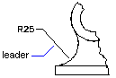
[CommandMethod("CreateLeader")] publicstaticvoidCreateLeader() { // Get the current database Document acDoc = Application.DocumentManager.MdiActiveDocument; Database acCurDb = acDoc.Database;
// Start a transaction using (Transaction acTrans = acCurDb.TransactionManager.StartTransaction()) { // Open the Block table for read BlockTable acBlkTbl; acBlkTbl = acTrans.GetObject(acCurDb.BlockTableId, OpenMode.ForRead) as BlockTable;
// Open the Block table record Model space for write BlockTableRecord acBlkTblRec; acBlkTblRec = acTrans.GetObject(acBlkTbl[BlockTableRecord.ModelSpace], OpenMode.ForWrite) as BlockTableRecord;
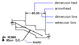
// Create the leader using (Leader acLdr = new Leader()) { acLdr.AppendVertex(new Point3d(0, 0, 0)); acLdr.AppendVertex(new Point3d(4, 4, 0)); acLdr.AppendVertex(new Point3d(4, 5, 0)); acLdr.HasArrowHead = true;
// Add the new object to Model space and the transaction acBlkTblRec.AppendEntity(acLdr); acTrans.AddNewlyCreatedDBObject(acLdr, true); }
// Commit the changes and dispose of the transaction acTrans.Commit(); } }
[CommandMethod("AddLeaderAnnotation")] publicstaticvoidAddLeaderAnnotation() { // Get the current database Document acDoc = Application.DocumentManager.MdiActiveDocument; Database acCurDb = acDoc.Database;
// Start a transaction using (Transaction acTrans = acCurDb.TransactionManager.StartTransaction()) { // Open the Block table for read BlockTable acBlkTbl; acBlkTbl = acTrans.GetObject(acCurDb.BlockTableId, OpenMode.ForRead) as BlockTable;
// Open the Block table record Model space for write BlockTableRecord acBlkTblRec; acBlkTblRec = acTrans.GetObject(acBlkTbl[BlockTableRecord.ModelSpace], OpenMode.ForWrite) as BlockTableRecord;
// Create the MText annotation using (MText acMText = new MText()) { acMText.Contents = "Hello, World."; acMText.Location = new Point3d(5, 5, 0); acMText.Width = 2;
// Add the new object to Model space and the transaction acBlkTblRec.AppendEntity(acMText); acTrans.AddNewlyCreatedDBObject(acMText, true);
// Create the leader with annotation using (Leader acLdr = new Leader()) { acLdr.AppendVertex(new Point3d(0, 0, 0)); acLdr.AppendVertex(new Point3d(4, 4, 0)); acLdr.AppendVertex(new Point3d(4, 5, 0)); acLdr.HasArrowHead = true;
// Add the new object to Model space and the transaction acBlkTblRec.AppendEntity(acLdr); acTrans.AddNewlyCreatedDBObject(acLdr, true);
// Attach the annotation after the leader object is added acLdr.Annotation = acMText.ObjectId; acLdr.EvaluateLeader(); } }
// Commit the changes and dispose of the transaction acTrans.Commit(); } }
[CommandMethod("CreateGeometricTolerance")] publicstaticvoidCreateGeometricTolerance() { // Get the current database Document acDoc = Application.DocumentManager.MdiActiveDocument; Database acCurDb = acDoc.Database;
// Start a transaction using (Transaction acTrans = acCurDb.TransactionManager.StartTransaction()) { // Open the Block table for read BlockTable acBlkTbl; acBlkTbl = acTrans.GetObject(acCurDb.BlockTableId, OpenMode.ForRead) as BlockTable;
// Open the Block table record Model space for write BlockTableRecord acBlkTblRec; acBlkTblRec = acTrans.GetObject(acBlkTbl[BlockTableRecord.ModelSpace], OpenMode.ForWrite) as BlockTableRecord;
// Create the Geometric Tolerance (Feature Control Frame) using (FeatureControlFrame acFcf = new FeatureControlFrame()) { acFcf.Text = "{\\Fgdt;j}%%v{\\Fgdt;n}0.001%%v%%v%%v%%v"; acFcf.Location = new Point3d(5, 5, 0);
// Add the new object to Model space and the transaction acBlkTblRec.AppendEntity(acFcf); acTrans.AddNewlyCreatedDBObject(acFcf, true); }
// Commit the changes and dispose of the transaction acTrans.Commit(); } }