using System.Drawing; using Autodesk.AutoCAD.Runtime; using Autodesk.AutoCAD.ApplicationServices; [CommandMethod("PositionApplicationWindow")] publicstaticvoidPositionApplicationWindow() { //设置cad窗口的位置,左上角为原点 Point ptApp = new Point(0, 0); Application.MainWindow.SetLocation(ptApp);
// 设置尺寸 Size szApp = new Size(400, 400); Application.MainWindow.SetSize(szApp); }
using System.Drawing; using Autodesk.AutoCAD.Runtime; using Autodesk.AutoCAD.ApplicationServices; using Autodesk.AutoCAD.Windows; [CommandMethod("MinMaxApplicationWindow")] publicstaticvoidMinMaxApplicationWindow() { //Minimize the Application window Application.MainWindow.WindowState = Window.State.Minimized;
//Maximize the Application window Application.MainWindow.WindowState = Window.State.Maximized; System.Windows.Forms.MessageBox.Show("Maximized", "MinMax"); }
查找应用程序窗口的当前状态
示例查询“应用程序”窗口的状态,并在消息框中向用户显示该状态。
1 2 3 4 5 6 7 8 9 10 11
using Autodesk.AutoCAD.Runtime; using Autodesk.AutoCAD.ApplicationServices; using Autodesk.AutoCAD.Windows; [CommandMethod("CurrentWindowState")] publicstaticvoidCurrentWindowState() { System.Windows.Forms.MessageBox.Show("The application window is " + Application.MainWindow.WindowState.ToString(), "Window State"); }
使应用程序窗口不可见和可见
下面的代码使用 Visible 属性使AutoCAD应用程序窗口不可见,然后再次可见。
1
2
3
4
5
6
7
8
9
10
11
12
13
14
15
using Autodesk.AutoCAD.Runtime; using Autodesk.AutoCAD.ApplicationServices; using Autodesk.AutoCAD.Windows; [CommandMethod("HideWindowState")] publicstaticvoidHideWindowState() { //Hide the Application window Application.MainWindow.Visible = false; System.Windows.Forms.MessageBox.Show("Invisible", "Show/Hide");
//Show the Application window Application.MainWindow.Visible = true; System.Windows.Forms.MessageBox.Show("Visible", "Show/Hide"); }
using Autodesk.AutoCAD.Runtime; using Autodesk.AutoCAD.ApplicationServices; using Autodesk.AutoCAD.Windows; [CommandMethod("SizeDocumentWindow")] publicstaticvoidSizeDocumentWindow() { //Size the Document window Document acDoc = Application.DocumentManager.MdiActiveDocument;
// Works around what looks to be a refresh problem with the Application window acDoc.Window.WindowState = Window.State.Normal;
// Set the position of the Document window System.Drawing.Point ptDoc = new System.Drawing.Point(0, 0); acDoc.Window.SetLocation(ptDoc);
// Set the size of the Document window System.Drawing.Size szDoc = new System.Drawing.Size(400, 400); acDoc.Window.SetSize(szDoc); }
最小化和最大化活动文档窗口
1 2 3 4 5 6 7 8 9 10 11 12 13 14 15 16 17
using Autodesk.AutoCAD.Runtime; using Autodesk.AutoCAD.ApplicationServices; using Autodesk.AutoCAD.Windows; [CommandMethod("MinMaxDocumentWindow")] publicstaticvoidMinMaxDocumentWindow() { Document acDoc = Application.DocumentManager.MdiActiveDocument;
//Minimize the Document window acDoc.Window.WindowState = Window.State.Minimized; System.Windows.Forms.MessageBox.Show("Minimized" , "MinMax");
using Autodesk.AutoCAD.Runtime; using Autodesk.AutoCAD.ApplicationServices; using Autodesk.AutoCAD.Windows; [CommandMethod("CurrentDocWindowState")] publicstaticvoidCurrentDocWindowState() { Document acDoc = Application.DocumentManager.MdiActiveDocument;
System.Windows.Forms.MessageBox.Show("The document window is " + acDoc.Window.WindowState.ToString(), "Window State"); }
using Autodesk.AutoCAD.ApplicationServices; using Autodesk.AutoCAD.DatabaseServices; using Autodesk.AutoCAD.Runtime; using Autodesk.AutoCAD.Geometry; staticvoidZoom(Point3d pMin, Point3d pMax, Point3d pCenter, double dFactor) { // Get the current document and database Document acDoc = Application.DocumentManager.MdiActiveDocument; Database acCurDb = acDoc.Database;
int nCurVport = System.Convert.ToInt32(Application.GetSystemVariable("CVPORT"));
// Get the extents of the current space when no points // or only a center point is provided // Check to see if Model space is current if (acCurDb.TileMode == true) { if (pMin.Equals(new Point3d()) == true && pMax.Equals(new Point3d()) == true) { pMin = acCurDb.Extmin; pMax = acCurDb.Extmax; } } else { // Check to see if Paper space is current if (nCurVport == 1) { // Get the extents of Paper space if (pMin.Equals(new Point3d()) == true && pMax.Equals(new Point3d()) == true) { pMin = acCurDb.Pextmin; pMax = acCurDb.Pextmax; } } else { // Get the extents of Model space if (pMin.Equals(new Point3d()) == true && pMax.Equals(new Point3d()) == true) { pMin = acCurDb.Extmin; pMax = acCurDb.Extmax; } } }
// Start a transaction using (Transaction acTrans = acCurDb.TransactionManager.StartTransaction()) { // Get the current view using (ViewTableRecord acView = acDoc.Editor.GetCurrentView()) { Extents3d eExtents;
// If a center point is specified, define the min and max // point of the extents // for Center and Scale modes if (pCenter.DistanceTo(Point3d.Origin) != 0) { pMin = new Point3d(pCenter.X - (acView.Width / 2), pCenter.Y - (acView.Height / 2), 0);
// Create an extents object using a line using (Line acLine = new Line(pMin, pMax)) { eExtents = new Extents3d(acLine.Bounds.Value.MinPoint, acLine.Bounds.Value.MaxPoint); }
// Calculate the ratio between the width and height of the current view double dViewRatio; dViewRatio = (acView.Width / acView.Height);
// Tranform the extents of the view matWCS2DCS = matWCS2DCS.Inverse(); eExtents.TransformBy(matWCS2DCS);
// Check to see if a center point was provided (Center and Scale modes) if (pCenter.DistanceTo(Point3d.Origin) != 0) { dWidth = acView.Width; dHeight = acView.Height;
if (dFactor == 0) { pCenter = pCenter.TransformBy(matWCS2DCS); }
pNewCentPt = new Point2d(pCenter.X, pCenter.Y); } else// Working in Window, Extents and Limits mode { // Calculate the new width and height of the current view dWidth = eExtents.MaxPoint.X - eExtents.MinPoint.X; dHeight = eExtents.MaxPoint.Y - eExtents.MinPoint.Y;
// Get the center of the view pNewCentPt = new Point2d(((eExtents.MaxPoint.X + eExtents.MinPoint.X) * 0.5), ((eExtents.MaxPoint.Y + eExtents.MinPoint.Y) * 0.5)); }
// Check to see if the new width fits in current window if (dWidth > (dHeight * dViewRatio)) dHeight = dWidth / dViewRatio;
// Resize and scale the view if (dFactor != 0) { acView.Height = dHeight * dFactor; acView.Width = dWidth * dFactor; }
// Set the center of the view acView.CenterPoint = pNewCentPt;
// Set the current view acDoc.Editor.SetCurrentView(acView); }
[CommandMethod("ZoomWindow")] staticpublicvoidZoomWindow() { // Zoom to a window boundary defined by 1.3,7.8 and 13.7,-2.6 Point3d pMin = new Point3d(1.3, 7.8, 0); Point3d pMax = new Point3d(13.7, -2.6, 0); Zoom(pMin, pMax, new Point3d(), 1); }
[CommandMethod("ZoomScale")] staticpublicvoidZoomScale() { // Get the current document Document acDoc = Application.DocumentManager.MdiActiveDocument; // Get the current view using (ViewTableRecord acView = acDoc.Editor.GetCurrentView()) { // Get the center of the current view Point3d pCenter = new Point3d(acView.CenterPoint.X, acView.CenterPoint.Y, 0); // Set the scale factor to use double dScale = 0.5; // Scale the view using the center of the current view Zoom(new Point3d(), new Point3d(), pCenter, 1 / dScale); } }
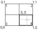
[CommandMethod("ZoomCenter")] staticpublicvoidZoomCenter() { // Center the view at 5,5,0 Zoom(new Point3d(), new Point3d(), new Point3d(5, 5, 0), 1); }
[CommandMethod("ZoomExtents")] staticpublicvoidZoomExtents() { // Zoom to the extents of the current space Zoom(new Point3d(), new Point3d(), new Point3d(), 1.01075); } [CommandMethod("ZoomLimits")] staticpublicvoidZoomLimits() { Document acDoc = Application.DocumentManager.MdiActiveDocument; Database acCurDb = acDoc.Database; // Zoom to the limits of Model space Zoom(new Point3d(acCurDb.Limmin.X, acCurDb.Limmin.Y, 0), new Point3d(acCurDb.Limmax.X, acCurDb.Limmax.Y, 0), new Point3d(), 1); }
using Autodesk.AutoCAD.ApplicationServices; using Autodesk.AutoCAD.DatabaseServices; using Autodesk.AutoCAD.Runtime; [CommandMethod("CreateNamedView")] publicstaticvoidCreateNamedView() { // Get the current database Document acDoc = Application.DocumentManager.MdiActiveDocument; Database acCurDb = acDoc.Database;
// Start a transaction using (Transaction acTrans = acCurDb.TransactionManager.StartTransaction()) { // Open the View table for read ViewTable acViewTbl; acViewTbl = acTrans.GetObject(acCurDb.ViewTableId, OpenMode.ForRead) as ViewTable;
// Check to see if the named view 'View1' exists if (acViewTbl.Has("View1") == false) { // Open the View table for write acTrans.GetObject(acCurDb.ViewTableId, OpenMode.ForWrite);
// Create a new View table record and name the view 'View1' using (ViewTableRecord acViewTblRec = new ViewTableRecord()) { acViewTblRec.Name = "View1";
// Add the new View table record to the View table and the transaction acViewTbl.Add(acViewTblRec); acTrans.AddNewlyCreatedDBObject(acViewTblRec, true);
// Set 'View1' current acDoc.Editor.SetCurrentView(acViewTblRec); }
using Autodesk.AutoCAD.ApplicationServices; using Autodesk.AutoCAD.DatabaseServices; using Autodesk.AutoCAD.Runtime; [CommandMethod("EraseNamedView")] publicstaticvoidEraseNamedView() { // Get the current database Document acDoc = Application.DocumentManager.MdiActiveDocument; Database acCurDb = acDoc.Database;
// Start a transaction using (Transaction acTrans = acCurDb.TransactionManager.StartTransaction()) { // Open the View table for read ViewTable acViewTbl; acViewTbl = acTrans.GetObject(acCurDb.ViewTableId, OpenMode.ForRead) as ViewTable;
// Check to see if the named view 'View1' exists if (acViewTbl.Has("View1") == true) { // Open the View table for write acTrans.GetObject(acCurDb.ViewTableId, OpenMode.ForWrite);
// Get the named view ViewTableRecord acViewTblRec; acViewTblRec = acTrans.GetObject(acViewTbl["View1"], OpenMode.ForWrite) as ViewTableRecord;
// Remove the named view from the View table acViewTblRec.Erase();
using Autodesk.AutoCAD.ApplicationServices; using Autodesk.AutoCAD.DatabaseServices; using Autodesk.AutoCAD.Runtime; using Autodesk.AutoCAD.Geometry; [CommandMethod("CreateModelViewport")] publicstaticvoidCreateModelViewport() { // Get the current database Document acDoc = Application.DocumentManager.MdiActiveDocument; Database acCurDb = acDoc.Database;
// Start a transaction using (Transaction acTrans = acCurDb.TransactionManager.StartTransaction()) { // Open the Viewport table for read ViewportTable acVportTbl; acVportTbl = acTrans.GetObject(acCurDb.ViewportTableId, OpenMode.ForRead) as ViewportTable;
// Check to see if the named view 'TEST_VIEWPORT' exists if (acVportTbl.Has("TEST_VIEWPORT") == false) { // Open the View table for write acTrans.GetObject(acCurDb.ViewportTableId, OpenMode.ForWrite);
// Add the new viewport to the Viewport table and the transaction using (ViewportTableRecord acVportTblRecLwr = new ViewportTableRecord()) { acVportTbl.Add(acVportTblRecLwr); acTrans.AddNewlyCreatedDBObject(acVportTblRecLwr, true);
// Name the new viewport 'TEST_VIEWPORT' and assign it to be // the lower half of the drawing window acVportTblRecLwr.Name = "TEST_VIEWPORT"; acVportTblRecLwr.LowerLeftCorner = new Point2d(0, 0); acVportTblRecLwr.UpperRightCorner = new Point2d(1, 0.5);
// Add the new viewport to the Viewport table and the transaction using (ViewportTableRecord acVportTblRecUpr = new ViewportTableRecord()) { acVportTbl.Add(acVportTblRecUpr); acTrans.AddNewlyCreatedDBObject(acVportTblRecUpr, true);
// Name the new viewport 'TEST_VIEWPORT' and assign it to be // the upper half of the drawing window acVportTblRecUpr.Name = "TEST_VIEWPORT"; acVportTblRecUpr.LowerLeftCorner = new Point2d(0, 0.5); acVportTblRecUpr.UpperRightCorner = new Point2d(1, 1);
// To assign the new viewports as the active viewports, the // viewports named '*Active' need to be removed and recreated // based on 'TEST_VIEWPORT'.
// Step through each object in the symbol table foreach (ObjectId acObjId in acVportTbl) { // Open the object for read ViewportTableRecord acVportTblRec; acVportTblRec = acTrans.GetObject(acObjId, OpenMode.ForRead) as ViewportTableRecord;
// See if it is one of the active viewports, and if so erase it if (acVportTblRec.Name == "*Active") { acTrans.GetObject(acObjId, OpenMode.ForWrite); acVportTblRec.Erase(); } }
// Clone the new viewports as the active viewports foreach (ObjectId acObjId in acVportTbl) { // Open the object for read ViewportTableRecord acVportTblRec; acVportTblRec = acTrans.GetObject(acObjId, OpenMode.ForRead) as ViewportTableRecord;
// See if it is one of the active viewports, and if so erase it if (acVportTblRec.Name == "TEST_VIEWPORT") { ViewportTableRecord acVportTblRecClone; acVportTblRecClone = acVportTblRec.Clone() as ViewportTableRecord;
// Add the new viewport to the Viewport table and the transaction acVportTbl.Add(acVportTblRecClone); acVportTblRecClone.Name = "*Active"; acTrans.AddNewlyCreatedDBObject(acVportTblRecClone, true); } }
// Update the display with the new tiled viewports arrangement acDoc.Editor.UpdateTiledViewportsFromDatabase(); } }
using Autodesk.AutoCAD.ApplicationServices; using Autodesk.AutoCAD.DatabaseServices; using Autodesk.AutoCAD.Runtime; using Autodesk.AutoCAD.Geometry; [CommandMethod("SplitAndIterateModelViewports")] publicstaticvoidSplitAndIterateModelViewports() { // Get the current database Document acDoc = Application.DocumentManager.MdiActiveDocument; Database acCurDb = acDoc.Database;
// Start a transaction using (Transaction acTrans = acCurDb.TransactionManager.StartTransaction()) { // Open the Viewport table for write ViewportTable acVportTbl; acVportTbl = acTrans.GetObject(acCurDb.ViewportTableId, OpenMode.ForWrite) as ViewportTable;
// Open the active viewport for write ViewportTableRecord acVportTblRec; acVportTblRec = acTrans.GetObject(acDoc.Editor.ActiveViewportId, OpenMode.ForWrite) as ViewportTableRecord;
using (ViewportTableRecord acVportTblRecNew = new ViewportTableRecord()) { // Add the new viewport to the Viewport table and the transaction acVportTbl.Add(acVportTblRecNew); acTrans.AddNewlyCreatedDBObject(acVportTblRecNew, true);
// Assign the name '*Active' to the new Viewport acVportTblRecNew.Name = "*Active";
// Use the existing lower left corner for the new viewport acVportTblRecNew.LowerLeftCorner = acVportTblRec.LowerLeftCorner;
// Get half the X of the existing upper corner acVportTblRecNew.UpperRightCorner = new Point2d(acVportTblRec.UpperRightCorner.X, acVportTblRec.LowerLeftCorner.Y + ((acVportTblRec.UpperRightCorner.Y - acVportTblRec.LowerLeftCorner.Y) / 2));
// Recalculate the corner of the active viewport acVportTblRec.LowerLeftCorner = new Point2d(acVportTblRec.LowerLeftCorner.X, acVportTblRecNew.UpperRightCorner.Y);
// Update the display with the new tiled viewports arrangement acDoc.Editor.UpdateTiledViewportsFromDatabase();
// Step through each object in the symbol table foreach (ObjectId acObjId in acVportTbl) { // Open the object for read ViewportTableRecord acVportTblRecCur; acVportTblRecCur = acTrans.GetObject(acObjId, OpenMode.ForRead) as ViewportTableRecord;
if (acVportTblRecCur.Name == "*Active") { Application.SetSystemVariable("CVPORT", acVportTblRecCur.Number);
Application.ShowAlertDialog("Viewport: " + acVportTblRecCur.Number + " is now active." + "\nLower left corner: " + acVportTblRecCur.LowerLeftCorner.X + ", " + acVportTblRecCur.LowerLeftCorner.Y + "\nUpper right corner: " + acVportTblRecCur.UpperRightCorner.X + ", " + acVportTblRecCur.UpperRightCorner.Y); } } }
// Commit the changes and dispose of the transaction acTrans.Commit(); } }
要创建新图形或打开现有图形,请使用 DocumentCollectionExtension 对象的方法。 Add 方法基于图形模板创建新的图形文件,并将该图形添加到 DocumentCollectionExtension 。 Open 方法打开现有的图形文件。
创建新图形
此示例使用 Add 方法基于acad.dwt图形样板文件创建新图形。
1 2 3 4 5 6 7 8 9 10 11 12 13 14 15 16
using Autodesk.AutoCAD.ApplicationServices; using Autodesk.AutoCAD.DatabaseServices; using Autodesk.AutoCAD.Runtime; [CommandMethod("NewDrawing", CommandFlags.Session)] publicstaticvoidNewDrawing() { // Specify the template to use, if the template is not found // the default settings are used. string strTemplatePath = "acad.dwt";
using System.IO; using Autodesk.AutoCAD.ApplicationServices; using Autodesk.AutoCAD.DatabaseServices; using Autodesk.AutoCAD.Runtime; [CommandMethod("OpenDrawing", CommandFlags.Session)] publicstaticvoidOpenDrawing() { string strFileName = "C:\\campus.dwg"; DocumentCollection acDocMgr = Application.DocumentManager;
if (File.Exists(strFileName)) { acDocMgr.Open(strFileName, false); } else { acDocMgr.MdiActiveDocument.Editor.WriteMessage("File " + strFileName + " does not exist."); } }
using Autodesk.AutoCAD.ApplicationServices; using Autodesk.AutoCAD.Runtime; [CommandMethod("SaveActiveDrawing")] publicstaticvoidSaveActiveDrawing() { Document acDoc = Application.DocumentManager.MdiActiveDocument; string strDWGName = acDoc.Name; object obj = Application.GetSystemVariable("DWGTITLED"); // Check to see if the drawing has been named if (System.Convert.ToInt16(obj) == 0) { // If the drawing is using a default name (Drawing1, Drawing2, etc) // then provide a new name strDWGName = "c:\\MyDrawing.dwg"; } // Save the active drawing acDoc.Database.SaveAs(strDWGName, true, DwgVersion.Current, acDoc.Database.SecurityParameters); }
using Autodesk.AutoCAD.ApplicationServices; using Autodesk.AutoCAD.DatabaseServices; using Autodesk.AutoCAD.Runtime; [CommandMethod("DrawingSaved")] publicstaticvoidDrawingSaved() { object obj = Application.GetSystemVariable("DBMOD"); // Check the value of DBMOD, if 0 then the drawing has no unsaved changes if (System.Convert.ToInt16(obj) != 0) { if (System.Windows.Forms.MessageBox.Show("Do you wish to save this drawing?", "Save Drawing", System.Windows.Forms.MessageBoxButtons.YesNo, System.Windows.Forms.MessageBoxIcon.Question) == System.Windows.Forms.DialogResult.Yes) { Document acDoc = Application.DocumentManager.MdiActiveDocument; acDoc.Database.SaveAs(acDoc.Name, true, DwgVersion.Current, acDoc.Database.SecurityParameters); } } }
using Autodesk.Windows; using Autodesk.AutoCAD.Runtime; using Autodesk.AutoCAD.ApplicationServices; // Create the command handler for the custom application menu item publicclassMyCommandHandler : System.Windows.Input.ICommand { publicboolCanExecute(object parameter) { returntrue; } publicevent EventHandler CanExecuteChanged; publicvoidExecute(object parameter) { Application.ShowAlertDialog("MyMenuItem has been clicked"); } } classChapter4 { //Global var for ZeroDocState ApplicationMenuItem acApMenuItem = null; [CommandMethod("AddZeroDocEvent")] publicvoidAddZeroDocEvent() { // Get the DocumentCollection and register the DocumentDestroyed event DocumentCollection acDocMgr = Application.DocumentManager; acDocMgr.DocumentDestroyed += new DocumentDestroyedEventHandler(docDestroyed); } publicvoiddocDestroyed(object obj, DocumentDestroyedEventArgs acDocDesEvtArgs) { // Determine if the menu item already exists and the number of documents open if (Application.DocumentManager.Count == 1 && acApMenuItem == null) { // Add the event handler to watch for when the application menu is opened // AdWindows.dll must be referenced to the project ComponentManager.ApplicationMenu.Opening += new EventHandler<EventArgs>(ApplicationMenu_Opening); } } voidApplicationMenu_Opening(object sender, EventArgs e) { // Check to see if the custom menu item was added previously if (acApMenuItem == null) { // Get the application menu component ApplicationMenu acApMenu = ComponentManager.ApplicationMenu; // Create a new application menu item acApMenuItem = new ApplicationMenuItem(); acApMenuItem.Text = "MyMenuItem"; acApMenuItem.CommandHandler = new MyCommandHandler(); // Append the new menu item acApMenu.MenuContent.Items.Add(acApMenuItem); // Remove the application menu Opening event handler ComponentManager.ApplicationMenu.Opening -= new EventHandler<EventArgs>(ApplicationMenu_Opening); } } }
using Autodesk.AutoCAD.ApplicationServices; using Autodesk.AutoCAD.DatabaseServices; using Autodesk.AutoCAD.Runtime; using Autodesk.AutoCAD.Geometry; [CommandMethod("LockDoc", CommandFlags.Session)] publicstaticvoidLockDoc() { // Create a new drawing DocumentCollection acDocMgr = Application.DocumentManager; Document acNewDoc = acDocMgr.Add("acad.dwt"); Database acDbNewDoc = acNewDoc.Database;
// Lock the new document using (DocumentLock acLckDoc = acNewDoc.LockDocument()) { // Start a transaction in the new database using (Transaction acTrans = acDbNewDoc.TransactionManager.StartTransaction()) { // Open the Block table for read BlockTable acBlkTbl; acBlkTbl = acTrans.GetObject(acDbNewDoc.BlockTableId, OpenMode.ForRead) as BlockTable;
// Open the Block table record Model space for write BlockTableRecord acBlkTblRec; acBlkTblRec = acTrans.GetObject(acBlkTbl[BlockTableRecord.ModelSpace], OpenMode.ForWrite) as BlockTableRecord;
// Create a circle with a radius of 3 at 5,5 using (Circle acCirc = new Circle()) { acCirc.Center = new Point3d(5, 5, 0); acCirc.Radius = 3;
// Add the new object to Model space and the transaction acBlkTblRec.AppendEntity(acCirc); acTrans.AddNewlyCreatedDBObject(acCirc, true); }
// Save the new object to the database acTrans.Commit(); }
// Unlock the document }
// Set the new document current acDocMgr.MdiActiveDocument = acNewDoc; }
using Autodesk.AutoCAD.ApplicationServices; using Autodesk.AutoCAD.Runtime; using Autodesk.AutoCAD.Interop; [CommandMethod("PrefsSetCursor")] publicstaticvoidPrefsSetCursor() { // This example sets the crosshairs for the drawing window // to full screen. // Access the Preferences object AcadPreferences acPrefComObj = (AcadPreferences)Application.Preferences; // Use the CursorSize property to set the size of the crosshairs acPrefComObj.Display.CursorSize = 100; }
隐藏滚动条
1 2 3 4 5 6 7 8 9 10 11 12 13 14 15
using Autodesk.AutoCAD.ApplicationServices; using Autodesk.AutoCAD.Runtime; using Autodesk.AutoCAD.Interop; [CommandMethod("PrefsSetDisplay")] publicstaticvoidPrefsSetDisplay() { // This example disables the scroll bars // Access the Preferences object AcadPreferences acPrefComObj = (AcadPreferences)Application.Preferences; // Disable the scroll bars acPrefComObj.Display.DisplayScrollBars = false; }
// Get the current value from a system variable
int nMaxSort = System.Convert.ToInt32(Application.GetSystemVariable("MAXSORT"));

// Set system variable to new value
Application.SetSystemVariable("MAXSORT", 100);
using Autodesk.AutoCAD.ApplicationServices; using Autodesk.AutoCAD.DatabaseServices; using Autodesk.AutoCAD.Runtime; using Autodesk.AutoCAD.Geometry; [CommandMethod("ChangeGridAndSnap")] publicstaticvoidChangeGridAndSnap() { // Get the current database Document acDoc = Application.DocumentManager.MdiActiveDocument; Database acCurDb = acDoc.Database; // Start a transaction using (Transaction acTrans = acCurDb.TransactionManager.StartTransaction()) { // Open the active viewport ViewportTableRecord acVportTblRec; acVportTblRec = acTrans.GetObject(acDoc.Editor.ActiveViewportId, OpenMode.ForWrite) as ViewportTableRecord; // Turn on the grid for the active viewport acVportTblRec.GridEnabled = true; // Adjust the spacing of the grid to 1, 1 acVportTblRec.GridIncrements = new Point2d(1, 1); // Turn on the snap mode for the active viewport acVportTblRec.SnapEnabled = true; // Adjust the snap spacing to 0.5, 0.5 acVportTblRec.SnapIncrements = new Point2d(0.5, 0.5); // Change the snap base point to 1, 1 acVportTblRec.SnapBase = new Point2d(1, 1); // Change the snap rotation angle to 30 degrees (0.524 radians) acVportTblRec.SnapAngle = 0.524; // Update the display of the tiled viewport acDoc.Editor.UpdateTiledViewportsFromDatabase(); // Commit the changes and dispose of the transaction acTrans.Commit(); } }
using Autodesk.AutoCAD.ApplicationServices; using Autodesk.AutoCAD.Runtime; using Autodesk.AutoCAD.Geometry; [CommandMethod("AngleFromXAxis")] publicstaticvoidAngleFromXAxis() { Point2d pt1 = new Point2d(2, 5); Point2d pt2 = new Point2d(5, 2); Application.ShowAlertDialog("Angle from XAxis: " + pt1.GetVectorTo(pt2).Angle.ToString()); }
using Autodesk.AutoCAD.ApplicationServices; using Autodesk.AutoCAD.DatabaseServices; using Autodesk.AutoCAD.Geometry; using Autodesk.AutoCAD.EditorInput; using Autodesk.AutoCAD.Runtime; [CommandMethod("CalculateDefinedArea")] publicstaticvoidCalculateDefinedArea() { // Prompt the user for 5 points Document acDoc = Application.DocumentManager.MdiActiveDocument; PromptPointResult pPtRes; Point2dCollection colPt = new Point2dCollection(); PromptPointOptions pPtOpts = new PromptPointOptions(""); // Prompt for the first point pPtOpts.Message = "\nSpecify first point: "; pPtRes = acDoc.Editor.GetPoint(pPtOpts); colPt.Add(new Point2d(pPtRes.Value.X, pPtRes.Value.Y)); // Exit if the user presses ESC or cancels the command if (pPtRes.Status == PromptStatus.Cancel) return; int nCounter = 1; while (nCounter <= 4) { // Prompt for the next points switch(nCounter) { case1: pPtOpts.Message = "\nSpecify second point: "; break; case2: pPtOpts.Message = "\nSpecify third point: "; break; case3: pPtOpts.Message = "\nSpecify fourth point: "; break; case4: pPtOpts.Message = "\nSpecify fifth point: "; break; } // Use the previous point as the base point pPtOpts.UseBasePoint = true; pPtOpts.BasePoint = pPtRes.Value; pPtRes = acDoc.Editor.GetPoint(pPtOpts); colPt.Add(new Point2d(pPtRes.Value.X, pPtRes.Value.Y)); if (pPtRes.Status == PromptStatus.Cancel) return; // Increment the counter nCounter = nCounter + 1; } // Create a polyline with 5 points using (Polyline acPoly = new Polyline()) { acPoly.AddVertexAt(0, colPt[0], 0, 0, 0); acPoly.AddVertexAt(1, colPt[1], 0, 0, 0); acPoly.AddVertexAt(2, colPt[2], 0, 0, 0); acPoly.AddVertexAt(3, colPt[3], 0, 0, 0); acPoly.AddVertexAt(4, colPt[4], 0, 0, 0); // Close the polyline acPoly.Closed = true; // Query the area of the polyline Application.ShowAlertDialog("Area of polyline: " + acPoly.Area.ToString()); // Dispose of the polyline } }
using Autodesk.AutoCAD.ApplicationServices; using Autodesk.AutoCAD.DatabaseServices; using Autodesk.AutoCAD.EditorInput; using Autodesk.AutoCAD.Geometry; using Autodesk.AutoCAD.Runtime; [CommandMethod("GetPointsFromUser")] publicstaticvoidGetPointsFromUser() { // Get the current database and start the Transaction Manager Document acDoc = Application.DocumentManager.MdiActiveDocument; Database acCurDb = acDoc.Database;
PromptPointResult pPtRes; PromptPointOptions pPtOpts = new PromptPointOptions("");
// Prompt for the start point pPtOpts.Message = "\nEnter the start point of the line: "; pPtRes = acDoc.Editor.GetPoint(pPtOpts); Point3d ptStart = pPtRes.Value;
// Exit if the user presses ESC or cancels the command if (pPtRes.Status == PromptStatus.Cancel) return;
// Prompt for the end point pPtOpts.Message = "\nEnter the end point of the line: "; pPtOpts.UseBasePoint = true; pPtOpts.BasePoint = ptStart; pPtRes = acDoc.Editor.GetPoint(pPtOpts); Point3d ptEnd = pPtRes.Value;
if (pPtRes.Status == PromptStatus.Cancel) return;
// Start a transaction using (Transaction acTrans = acCurDb.TransactionManager.StartTransaction()) { BlockTable acBlkTbl; BlockTableRecord acBlkTblRec;
// Open Model space for write acBlkTbl = acTrans.GetObject(acCurDb.BlockTableId, OpenMode.ForRead) as BlockTable;
acBlkTblRec = acTrans.GetObject(acBlkTbl[BlockTableRecord.ModelSpace], OpenMode.ForWrite) as BlockTableRecord;
// Define the new line using (Line acLine = new Line(ptStart, ptEnd)) { // Add the line to the drawing acBlkTblRec.AppendEntity(acLine); acTrans.AddNewlyCreatedDBObject(acLine, true); }
// Zoom to the extents or limits of the drawing acDoc.SendStringToExecute("._zoom _all ", true, false, false);
// Commit the changes and dispose of the transaction acTrans.Commit(); } }
using Autodesk.AutoCAD.ApplicationServices; using Autodesk.AutoCAD.EditorInput; using Autodesk.AutoCAD.Runtime; [CommandMethod("GetKeywordFromUser")] publicstaticvoidGetKeywordFromUser() { Document acDoc = Application.DocumentManager.MdiActiveDocument;
PromptKeywordOptions pKeyOpts = new PromptKeywordOptions(""); pKeyOpts.Message = "\nEnter an option "; pKeyOpts.Keywords.Add("Line"); pKeyOpts.Keywords.Add("Circle"); pKeyOpts.Keywords.Add("Arc"); pKeyOpts.AllowNone = false;
using Autodesk.AutoCAD.ApplicationServices; using Autodesk.AutoCAD.EditorInput; using Autodesk.AutoCAD.Runtime; [CommandMethod("GetKeywordFromUser2")] publicstaticvoidGetKeywordFromUser2() { Document acDoc = Application.DocumentManager.MdiActiveDocument;
PromptKeywordOptions pKeyOpts = new PromptKeywordOptions(""); pKeyOpts.Message = "\nEnter an option "; pKeyOpts.Keywords.Add("Line"); pKeyOpts.Keywords.Add("Circle"); pKeyOpts.Keywords.Add("Arc"); pKeyOpts.Keywords.Default = "Arc"; pKeyOpts.AllowNone = true;
using Autodesk.AutoCAD.ApplicationServices; using Autodesk.AutoCAD.EditorInput; using Autodesk.AutoCAD.Runtime; [CommandMethod("GetIntegerOrKeywordFromUser")] publicstaticvoidGetIntegerOrKeywordFromUser() { Document acDoc = Application.DocumentManager.MdiActiveDocument;
PromptIntegerOptions pIntOpts = new PromptIntegerOptions(""); pIntOpts.Message = "\nEnter the size or ";
// Restrict input to positive and non-negative values pIntOpts.AllowZero = false; pIntOpts.AllowNegative = false;
// Define the valid keywords and allow Enter pIntOpts.Keywords.Add("Big"); pIntOpts.Keywords.Add("Small"); pIntOpts.Keywords.Add("Regular"); pIntOpts.Keywords.Default = "Regular"; pIntOpts.AllowNone = true;
// Get the value entered by the user PromptIntegerResult pIntRes = acDoc.Editor.GetInteger(pIntOpts);
using Autodesk.AutoCAD.ApplicationServices; using Autodesk.AutoCAD.Runtime; [CommandMethod("SendACommandToAutoCAD")] publicstaticvoidSendACommandToAutoCAD() { Document acDoc = Application.DocumentManager.MdiActiveDocument; // Draws a circle and zooms to the extents or // limits of the drawing acDoc.SendStringToExecute("._circle 2,2,0 4 ", true, false, false); acDoc.SendStringToExecute("._zoom _all ", true, false, false); }