
27机电工程
机电工程
为了支持Revit软件的MEP工程功能,API提供了对Revit模型中HVAC和管道数据的读写访问,包括:
- 在系统中穿过风管、管道、管件和接头
- 添加、删除和更改风管、管道和其他设备
- 获取和设置系统属性
- 确定系统是否连接良好
- 访问机械设置
- 管理布管配置
本节中的页面
- MEP元素创建
- MEP系统
- 连接器
- MEP预制件详述
- 族创建
- 机械设置
- 电气设置
- 布管系统配置
MEP元素创建
可以使用Revit API创建MEP图元。
可以使用Autodesk.Revit.Creation.Document类中提供的以下方法创建与风管、管道和电气系统相关的许多图元:
- NewFlexDuct
- NewFlexPipe
- NewMechanicalSystem
- NewPipingSystem
- NewCrossFitting
- NewElbowFitting
- NewTakeoffFitting
- NewTeeFitting
- NewTransitionFitting
- NewUnionFitting
其他MEP元素(如管道)只能使用其对应类的静态Create()方法创建。某些MEP图元(如风管)可以通过相应类(即Duct)的静态方法或Autodesk.Revit.Creation.Document类的方法创建。对于这些元素,静态Create()方法是首选。
Duct 管道
- FlexDuct
- Pipe
- FlexPipe
- PipingSystem
- Wire
Pages in this section 本节中的页面
- 创建管道和风管
- 创建导线
- 占位符
- 创建系统
创建管道和风管
有三种方法可以创建新风管:软风管、管道和软管。它们可以在两点之间、两个连接件之间或点与连接件之间创建。
下面的代码使用Pipe.Create()方法在两点之间创建一个新管道。新的软管、风管和软风管都可以类似地创建。
代码区域:使用静态Create()方法创建新管道
1 | public Pipe CreateNewPipe(Document document, ElementId systemTypeId, ElementId levelId) |
下面的代码区域演示了如何使用静态FlexPipe.Create()方法创建FlexPipe。管道、风管和软风管都可以类似地在两点之间创建。
代码区域:使用静态Create()方法创建新的FlexPipe
1 | public FlexPipe CreateFlexPipe(Document document, Level level) |
创建管道后,可能需要修改直径。“管道”的“直径”属性为只读。要更改直径,请获取RBS_PIPE_DIAMETER_PARAM内置参数。
代码区域:更改管道直径
1 | public void ChangePipeSize(Pipe pipe) |
创建新风管或管道的另一种常用方法是在两个现有连接件之间创建,如下例所示。在本示例中,假设已在Revit中选择了2个带有接头的图元代码区域:在两个连接件之间添加风管其中一个是机械设备,另一个是风管管件,其接头与设备上的SupplyAir接头对齐。
代码区域:在两个连接件之间添加风管
1 | public Duct CreateDuctBetweenConnectors(UIDocument uiDocument) |
衬里和绝缘
可以将管道和风管保温层和内衬作为与风管和管道关联的单独对象添加。可以使用静态方法InsulationLiningBase.GetInsulationIds()检索与风管或管道关联的隔热层图元的ID,而可以使用静态方法InsulationLiningBase.GetLiningIds()检索衬里图元的ID。
若要创建与给定风管、管道、管件、附件或内容关联的新隔热层,请使用相应的静态方法:DuctInsulation.Create()或PipeInsulation.Create()。DuctLining.Create()可用于创建应用于给定风管、管件或附件内部的衬里的新实例。
创建导线
可以使用Revit API创建新的导线。
静态Wire.Create()允许在文档中创建新的连接。Create()方法需要新创建的关联在其中可见的视图的id。它必须是楼层平面或天花板投影平面视图的ID。导线的WiringType可以是Arc(隐藏在墙、天花板或楼板内的布线)或Chamfer(暴露的布线)。
导线的位置由定义导线顶点的XYZ点列表以及可选的起始和/或结束连接器指定。端点连接器可以为空,但是,如果指定了起始连接器,则连接器的原点将作为起点添加到导线的顶点。同样,如果指定了端点连接器,则连接器的原点将作为端点添加到导线的顶点。静态方法Wire.AreVertexPointsValid()将检查XYZ点以及起始和结束连接器的列表,以确保它们适合于导线。
导线的形状由导线的布线类型以及通过顶点和端点连接器提供的点的总数确定。如果布线类型为WiringType.Arc:
- 如果总共提供了2个点,则导线为直线导线。
- 如果总共提供3个点,则导线为圆弧导线。
- 如果有4个或更多点,则导线为样条线导线。
如果布线类型为WiringType.Chamfer,则将创建一条连接所有点的连接线。
下面的示例在活动视图中创建一条新的直线导线,但未指定任何连接器。
代码区域:创建新导线
1 | public Wire CreateWire(Document document) |
连接器
若要在创建后将关联连接到元素,请调用Wire.ConnectTo(),并传入开始和结束连接器。如果使用此方法时导线已经连接,则旧连接将断开,导线将连接到新目标。
顶点
创建线框后,可以使用Wire.GetVertex()方法检索顶点。这个方法接受一个请求顶点的索引,这个索引应该在0和Wire.NumberOfVertices(包括线的起点和终点)之间。
使用Wire. InsertVertex()将顶点添加到列表的末尾,或使用Wire.InsertVertex()将顶点添加到列表中的特定点。IsVertexPointValid()方法检查给定的顶点是否可以添加到该线。如果因为视图平面上的此位置已存在顶点(在公差范围内)而无法添加点,IsVertexPointValid()将返回false。请注意,如果开始顶点已经连接到元素,则不能在开始顶点之前插入顶点。类似地,如果端点已经连接到元素,则不能将顶点附加到列表的末尾。
Wire.RemoveVertex()将从列表中删除顶点。如果导线顶点已连接到元素,则此方法将无法删除该顶点。为了移除此顶点,应先断开连接,然后移除,然后重新连接(如果需要)。
占位符
占位符风管和管道
Revit API提供了在尚不清楚布局的确切设计时将占位符元素放入系统的功能。使用占位符风管和管道可以在设计仍然未知的情况下实现良好的连接系统,然后可以在后期的最终设计中进行详细说明。
两个静态方法Duct.Placeholder()和Pipe.Placeholder()创建占位符元素。风管和管道的IsPlaceholder属性指示它们是否为占位符元素。
准备从占位符创建实际风管和管道时,请使用Mechanical Utils.ConvertDuctPlaceholders()和PlumbingUtils.ConvertPipePlaceholders()方法将一组占位符元素转换为风管和管道。一旦转换成功,占位符元素将被删除。将创建新风管、管道和管件图元,并建立连接。
创建系统
创建电气、机械和管道系统。
Mechanical System和PipingSystem具有静态重载Create()方法,可用于创建新的机械系统或管道系统。这是创建新MEP系统的首选方法。这两个类的最简单Create()重载在给定文档中创建一个具有给定类型ID(对于Mechanical System,该ID应为DuctSystemType的ID,对于PipingSystem,该ID应为PipeSystemType的ID)的新系统。这两个类都有第二个Create()重载,它也接受系统的名称。创建元素后,可以使用MEPSystem.Add()方法将其添加到系统中。
还可以使用NewMechanicalSystem()和NewPipingSystem()从Creation.Document类创建MechanicalSystem和PipingSystem。NewPipingSystem()和NewMechanicalSystem()都采用作为基本设备连接器的连接器,例如管道系统的热水器或机械系统的风扇。它们还采用将添加到系统中的连接件(如管道系统中水槽上的连接件)的ConnectorSet。创建新系统所需的最后一项信息是NewPipingSystem()的PipeSystemType或NewMechanical System()的DuctSystemType。
可以使用ElectricalSystem.Create方法创建电气系统,该方法有两个重载。从一个未使用的Connector创建一个新的ElectricalSystem元素。另一个从一组电气元件创建一个新的ElectricalSystem元素。这两个重载都需要ElectricalSystemType。
在以下示例中,将从选定的机械设备(如风扇)和所有选定的风道末端创建新的SupplyAir风管系统。
代码区域:创建新的机械系统
1 | // create a connector set for new mechanical system |
MEP系统
MEPSystem是Revit MEP中电气、机械和管道系统的基类。
ElectricalSystem、MechanicalSystem和PipingSystem都派生自MEP System类。基类具有一些跨系统类型的通用功能,例如向系统添加元素或查找系统的基础面板或设备。基类中的一些方法仅适用于HVAC和管道系统,例如DivideSystem()方法,它划分系统中的物理网络并为每个网络创建一个新系统。
派生类具有特定于系统类型的其他方法和属性。
MEP截面
MEPSystem类有一个SectionsCount属性,该属性返回系统截面的节数。可以使用GetSectionByIndex()方法或GetSectionByNumber()方法获取MEPSection对象。虽然这些方法在MEP System基类中,但MEP Section类表示风管和管道部分,主要用于压力损失计算。它是一系列连接的图元(管段-风管或管道、管件、端子和附件),可以从GetElementIds()方法获得。所有截面构件应具有相同的流动分析特性:流量、尺寸、速度、摩擦力和粗糙度。
截面中每个元件的段长度、压降和损失系数可能不同,因此在MEP截面中提供了方法,以获得给定截面中某个元件的特定元件ID的这些值。管道的系数是损失系数。对于管道,这与摩擦系数相同。
计算
MEP系统的某些属性是由Revit计算的。Mechanical System和PipingSystem都具有IsWellConnected属性,该属性指示系统是否连接良好。如果系统连接不好,需要计算的参数无效。
对于机械和管道系统,某些值是根据系统截面的特性计算的。MEPSystem.GetCriticalPathSectionNumbers()方法按流动方向的顺序返回关键路径部分编号的列表,PressureLossOfCriticalPath()获取关键路径中部分的总压力损失。
Mechanical System和PipingSystem中的GetFlow()和GetStaticPressure()方法可获取系统的流量和静压。
PipingSystem具有其他计算属性:GetFixtureUnits()和GetVolume()
注意:由于Revit内部处理这些计算属性的方式,它们不支持动态模型更新。但是,其他未计算的系统属性支持动态模型更新。
连接器
连接件与域(风管、管道或电气)关联,该域可从连接件的“域”特性中获取。连接器存在于机械设备以及导管和管道上。
要遍历系统,可以检查系统基本设备上的连接器,并通过检查IsConnected属性和AllRefs属性来确定连接器附着的内容。在查找物理连接时,检查连接器的ConnectionType非常重要。Revit中既有物理连接器,也有逻辑连接器,但在应用程序中仅物理连接器可见。下面的图像显示了两种类型的物理连接器-端点连接和曲线连接器。
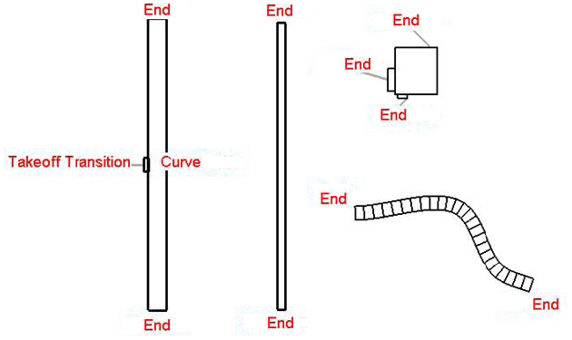
图167:物理连接器
下面的示例说明如何确定连接器的所有者,以及连接器与连接类型沿着的内容(如果有)。
代码区域30-5:确定连接器连接的内容
1 | public void GetElementAtConnector(Autodesk.Revit.DB.Connector connector) |
下面的对话框是在管道设备的连接器上运行此代码示例的结果。
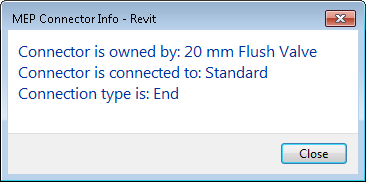
图168:连接器信息
MEP预制件详述
多个Revit API类共同提供将预制构件添加到Revit文档的功能。
预制详细类
在MEP模型中放置预制零件之前,必须指定预制件配置并将预制件服务加载到模型中。Revit API中有许多类可用于简化此过程,其中包括:
- FabricationConfiguration - 包含有关项目使用的预制件配置设置的信息。
- FabricationConfigurationInfo - 包含有关FabricationConfiguration属性的信息。
- ConfigurationReloadInfo - 包含重新加载FabricationConfiguration的结果。
- ConnectionValidationInfo -包含通过重新加载FabricationConfiguration生成的与连接相关的警告。
- FabricationService - 预制件配置的一部分,并定义可以使用哪些FabricationService。
- FabricationServiceButton - 定义在不同条件下使用哪些项。
- FabricationPart - 表示Revit中的预制构件。
- FabricationPartType - 定义FabricationPart的类型。
- FabricationRodInfo - 提供FabricationPart的杆信息。
- FabricationHostedInfo - 包含FabricationPart的主机信息,并提供从主机断开连接的功能。
- FabricationConnectorInfo - 包含有关FabricationPart的连接器的信息。
- FabricationUtils - Autodesk Revit产品中用于预制件的常规实用程序方法。
- FabricationDimensionDefinition - 包含有关预制件尺寸的信息。
MEP预制件中涉及的主要类别将在下文中详细介绍。可以在Revit SDK的FabricationPartLayout示例中找到示例代码。
预制件配置
使用FabricationConfiguration类,用户可以获取和设置文档的装配配置设置。他们还可以加载和卸载服务、重新加载预制件配置、获取加载的服务、获取预制件规范、从配置中获取材料和绝缘信息以及获取连接器信息。
文档只有一个装配配置,您可以使用静态FabricationConfiguration.GetFabricationConfiguration()方法获取它。要更改配置,请调用重载的SetConfiguration()方法,传入包含有关FabricationConfiguration的信息的FabricationConfiguration Info对象。SetConfiguration()方法的一个重载将使用全局概要文件设置配置,另一个重载接受概要文件名称并使用该特定概要文件设置配置。(The FabricationConfiguration.GetProfile()方法和FabricationConfigurationInfo.GetProfiles()方法分别返回与加载的配置或所有配置关联的配置文件。)
方法的作用是:从源加工配置中重新加载加工配置。这必须在加载预制件服务之前完成。
使用GetAllLoadedServices()方法获取所有加载的服务,或使用GetAllUsedServices()方法仅获取使用的预制件服务。如果服务中的任何预制件部件是由用户创建的,则服务正在使用中。这两个方法都返回FabricationService对象的列表。
LoadServices()和UnloadServices()可分别用于加载和卸载预制件服务列表。
FabricationConfiguration类还具有获取配置数据缩写的方法。GetMaterialAbbreviation()返回材质或隔热层或双层壁材质的缩写。GetSpecificationAbbreviation()返回给定规范的规范缩写,GetInsulationSpecificationAbbreviation()将返回给定绝缘规范的缩写。
预制件服务
预制零件服务是预制零件配置的一部分,定义可以使用哪些预制零件服务按钮。GroupCount属性返回服务中的组数。使用组的索引,可以调用GetGroupName()来获取组的名称。方法GetButtonCount()将返回指定组中的按钮数量,实际按钮可以通过调用GetButton()与指定的组索引和按钮索引来检索。
预制件服务按钮
FabricationServiceButton类包含有关预制件按钮的信息。预制件服务按钮定义可用于定义FabricationPart的项目,可能受特定条件列表的约束。预制零件服务按钮是预制件服务的一部分。
预制零件
使用FabricationPart类,用户可以在Revit模型中创建、放置、移动和对齐预制零件。用户还可以获取或设置预制零件的尺寸,并获取预制托管信息和杆信息。
重载的静态FabricationPart.Create()方法基于预制服务按钮创建一个新的预制零件。重载的静态Hanger()方法在另一个预制零件上创建一个悬挂件。静态AlignPartByConnectors()方法将移动预制零件,并通过其中一个连接器将其与另一个连接器对齐。
也可以使用DesignToFabricationConverter类从设计元素创建FabricationParts。Convert()方法将一组MEP设计元素转换为预制零件。可以使用GetConvertedFabricationParts()方法获取成功创建的FabricationParts。如果Convert()方法指示部分失败,则GetPartialConvertFailureResults()方法将返回可能失败的列表。对于部分故障类型(例如InvalidConnections),DesignToFabricationConverter类有一个对应的方法来检索具有该错误类型的FabricationParts的ElementId列表(例如GetConvertedFabricationPartsWithInvalidConnections())。
还存在获得和设置预制尺寸的值、获得主元件信息和获得预制杆信息的方法。
连接和位置
FabricationPart有许多方法可以附加到连接器或更改FabricationPart的位置。静态StretchAndFit()方法支持从指定的连接器拉伸加工零件并装配到目标布线端的操作。路由端表示为FabricationPartRouteEnd对象,该对象可以从静态FabricationPartRouteEnd. fromConnector()或FabricationPartRouteEnd. fromCenterline()方法中获取。如果StretchAndFit()方法失败,它将返回一个FabricationPartFitResult枚举,该枚举提供有关失败的更多详细信息。
修改FabricationPart的其他方法包括Reposition()、RotateConnectedPartByConnector()和PlaceAsTap()。
产品清单
某些FabricationPart图元(如购买的风管和管件)具有“产品列表”。产品列表条目表示选定零件的可用尺寸的目录。ProductListEntry属性指定FabricationPart的产品列表项。如果IsProductList()方法返回false,ProductListEntry将为-1。
要获取FabricationPart的产品条目列表,请使用GetProductListEntryCount()和GetProductListEntryName()方法。在更改FabricationPart的ProductListEntry之前,请调用IsProductListEntryEntrySize()以检查是否可以将此Part更改为指定的产品列表条目而不更改任何连接的尺寸。
族创建
在Revit族文档中创建机械设备时,需要添加接头以允许设备连接到系统。风管、电气和管道连接件都可以类似的方式添加,方法是使用将放置连接件的参照平面和连接件的系统类型。
ConnectorElement类提供的重载静态方法有:
- CreateCableTrayConnector
- CreateConduitConnector
- CreateDuctConnector
- CreateElectricalConnector
- CreatePipeConnector
上面的每个方法都有第二个重载,该重载接受一个附加的Edge参数,该参数允许创建以给定面的内部循环为中心的连接器元素。下面的代码演示如何将两个管道连接件添加到拉伸上的面,并设置它们的一些属性。
代码区域30 - 6:添加管道连接件
1 | public void CreatePipeConnectors(UIDocument uiDocument, Extrusion extrusion) |
下图说明了在使用“机械设备”样板创建的新族文档中运行此示例并传入拉伸2’×2’× 1 ‘的结果。请注意,连接件放置在平面的质心处。
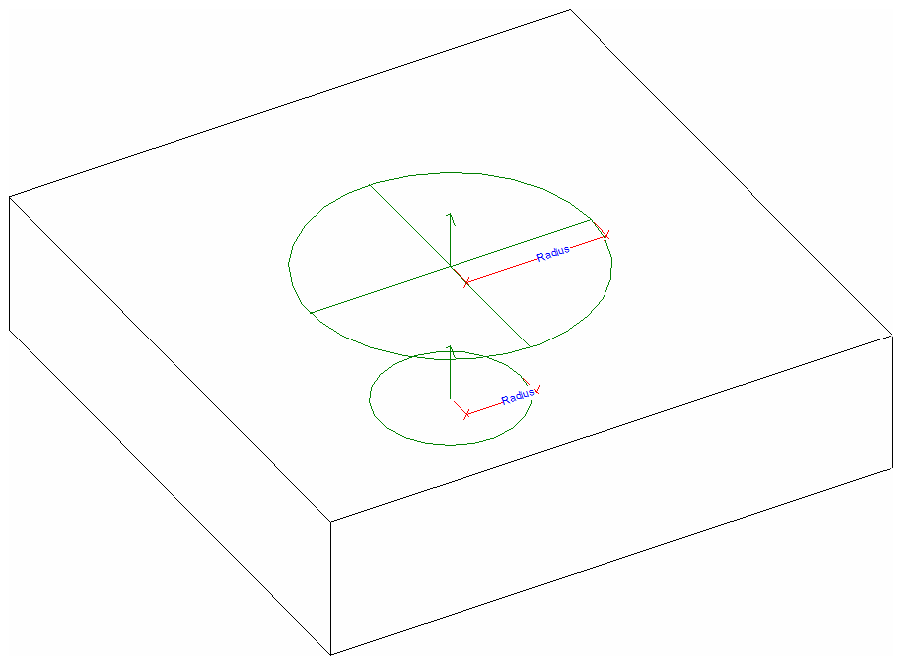
图169:在拉伸上创建的两个连接器
机械设置
“MEP设置-机械设置”下的“管理”选项卡上提供的许多设置也可通过Revit API使用。
管道设置
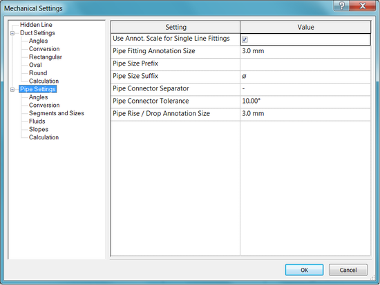
管道设置
PipeSettings类提供对上面显示的设置的访问,例如“管道尺寸后缀”和“管道接头公差”。每个文档都有一个PipeSettings对象,可以通过静态方法PipeSettings.GetPipeSettings()访问该对象。
拟合角度
管道的管件角度使用设置可从PipeSettings类的以下属性和方法中获得:
- PipeSettings.FittingAngleUsage
- PipeSettings.GetSpecificFittingAngles()
- PipeSettings.GetSpecificFittingAngleStatus()
- PipeSettings.SetSpecificFittingAngleStatus()
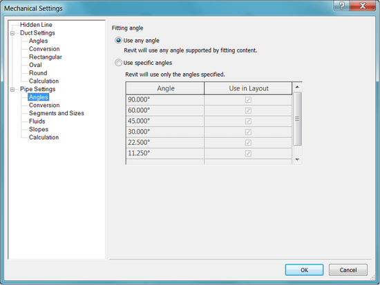
管件角度
分段和尺寸
UI中的“管道设置-分段和尺寸”下的设置也可用。
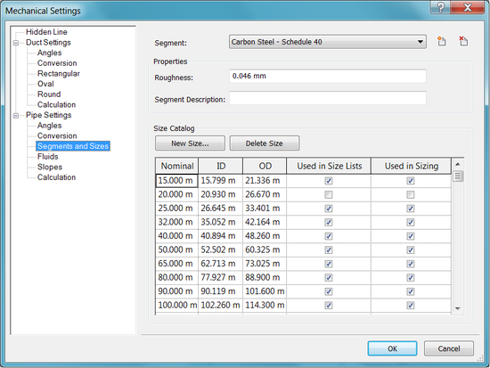
分段和尺寸
此信息可通过Segment和MEPSize类获得。段表示包含材质和一组可用尺寸的MEPCurve的长度。管道尺寸由MEPSize类表示。可用的段可以使用过滤器找到。下面的例子演示了如何在上面的对话框中获取一些信息。
代码区域:管道设置中的导线测量管道尺寸
1 | FilteredElementCollector collectorPipeType = new FilteredElementCollector(document); |
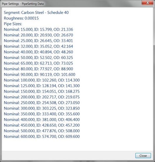
上一个示例的输出
若要向列表中添加新大小,请使用Segment.AddSize()方法。使用Segment.RemoveSize()按公称直径删除尺寸。
坡度
PipeSettings类还提供对UI中“管道设置-坡度”下可用坡度值的访问。使用GetPipeSlopes()检索坡度值列表。PipeSettings.SetPipeSlopes()提供一次设置所有坡度值的功能,而PipeSettings.AddPipeSlope()添加单个管道坡度。Revit将坡度值存储为百分比(0-100)。
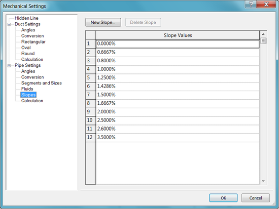
管道坡度值
风管设置
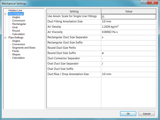
风管设置
通过DuctSettings类可以访问上面显示的设置,例如“风管管件注释尺寸”和“空气密度”。每个文档都有一个DuctSettings对象,可以通过静态方法DuctSettings.GetDuctSettings()访问该对象。
风管管件角度
风管的管件角度使用设置可从DuctSettings类的以下特性和方法中获得:
- DuctSettings.FittingAngleUsage
- DuctSettings.GetSpecificFittingAngles()
- DuctSettings.GetSpecificFittingAngleStatus()
- DuctSettings.SetSpecificFittingAngleStatus()
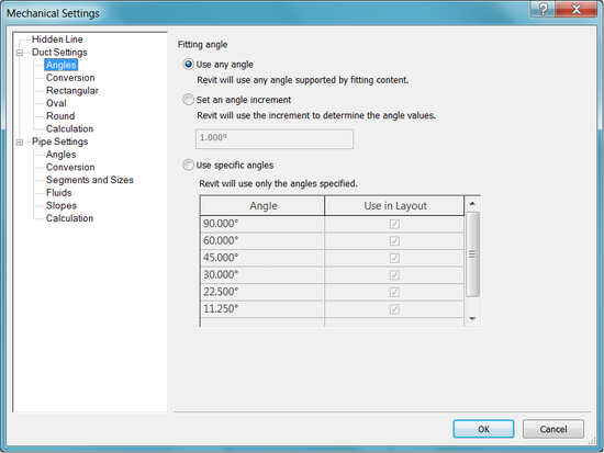
风管管件角度
电气设置
在“MEP设置-电气设置”下的“管理”选项卡上提供的某些设置也可通过Revit API使用。
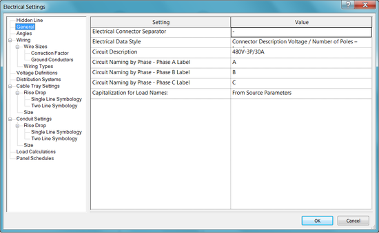
电气设置
ElectricalSettings类提供对不同电气设置的访问,例如管件角度、导线类型和电压类型。每个文档都有一个ElectricalSettings对象,可以通过静态方法ElectricalSetting.GetElectricalSettings()访问该对象。
常规设置
以下常规设置可用作ElectricalSetting类的属性:
- CircuitSequence - 访问回路序列编号模式
- CircuitNamePhaseA - 按相位访问回路命名(相位A标签)。
- CircuitNamePhaseB -按相位访问回路命名(相位B标签)。
- CircuitNamePhaseC - 按相位访问回路命名(相位C标签)。
拟合角度
电缆桥架和套管的装配角度设置可通过以下ElectricalSettings类的方法获得:
- GetSpecificFittingAngles()
- GetSpecificFittingAngleStatus()
- SetSpecificFittingAngleStatus()
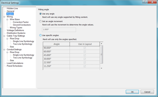
拟合角度
其他电气设置
ElectricalSetting类的属性提供对以下内容的访问:
- Distribution System Types 配电系统类型
- Voltage Types 电压类型
- Wire Conduit Types 导线管类型
- Wire Material Types 线材类型
- Wire Types 导线类型
还可以使用方法在项目中添加或删除配电系统类型、电压类型、导线材质类型和导线类型。
布管系统配置
布管系统配置可以通过RollingPreferenceManager类访问。此类的实例可从MEPCurveType类的属性中获得。目前,只有PipeType和DuctType支持布管系统配置。
ChalleningPreferenceManager管理用于选择段类型和尺寸以及基于用户选择标准的管接头类型的所有规则。ExcluingPreferenceRule类管理一个管段或管接头首选项,该类的实例可以添加到ExcluingPreferenceManager中。每个工艺路线首选项规则根据管理的工艺路线物料类型进行分组。该类型由PreferenceRuleGroupType表示,并包括以下选项:
| **Member name ** | **Description ** |
|---|---|
| Undefined | 未定义的组类型(默认初始值) |
| Segments | 分段类型(例如:管材) |
| Elbows | 弯头类型 |
| Junctions | 接头类型(例如接头、T形接头、Y形接头、分接头) |
| Crosses | 交叉类型 |
| Transitions | 过渡类型(请注意,多形状过渡可能有自己的组) |
| Unions | 将两个段连接在一起的联合类型 |
| MechanicalJoints | 将管接头连接到管接头、管段连接到管接头或管段连接到管段的机械联接类型 |
| TransitionsRectangularToRound | 从矩形型材到圆形型材的多形状过渡 |
| TransitionsRectangularToOval | 从矩形型材到椭圆形型材的多种形状过渡 |
| TransitionsOvalToRound | 从椭圆形轮廓到圆形轮廓的多种形状过渡 |
每个布管系统配置规则都可以具有一个或多个选择条件(由PrimaryCriterionBase类和派生类型PrimarySizeCriterion表示)。PrimarySizeCriterion基于最小和最大尺寸约束选择管件和管段。 BullingConditions类保存BullingCondition实例的集合。BullingCondition类表示在确定是否满足布线条件(如最小或最大直径)时用作输入的布线信息。GetMEPPartId()方法基于一个PreferenceRuleGroupType和PreferenceConditions获取一个管接头或管段ID。 以下示例获取文档中的所有管道类型,获取每种管道类型的布管系统配置管理器,然后根据布管系统配置管理器中的规则获取每个管段的尺寸。
代码区域:使用布管系统配置
1 | private List GetAvailablePipeSegmentSizesFromDocument(Document document) |