基准和信息元素

本章介绍Revit中的基准元素和信息元素。

  • 基准元素包括标高、轴网和模型线。
  • 信息元素包括阶段、设计选项和EnergyDataSettings。

有关Revit图元分类的详细信息,请参见图元要素。

注:如果您需要更多信息,请参阅相关章节:

  • 有关荷载基础、荷载工况、荷载组合、荷载性质和荷载用途,请参阅结构工程
  • 对于模型曲线,请参阅草图
  • 对于材质和填充图案,请参阅材质
  • 有关能量数据设置,请参阅能量数据

本节中的页面

  • Levels 标高
  • Grids 轴网
  • Phase 阶段
  • Design Options 设计选项

标高

标高是一个有限的水平面,用作以标高为主体的图元(如墙、屋顶、楼板和天花板)的参照。

在Revit Platform API中,Level类派生自DatumPlane类,而DatumPlane类派生自Element类。继承的Name属性用于检索Revit UI中标高编号旁边的用户可见标高名称。若要检索项目中的所有标高,请将ElementClassFilter与Level类一起使用。

高程

Level类具有以下属性:

  • “高程”特性用于检索或更改高于或低于地平面的高程。
  • ProjectElevation属性用于检索相对于项目原点的高程,而不考虑高程基准参数值。
  • “高程基准”值是一个标高类型参数。
    • 它的内置参数是LEVEL_RELATIVE_BASE_TYPE。
    • 它的类型是整型
    • 0对应于项目,1对应于共享。

下面的代码示例阐释如何使用Level类筛选器检索项目中的所有标高。

代码区域15-1:检索所有标高

1
2
3
4
5
6
7
8
9
10
11
12
13
14
15
16
17
18
19
20
21
22
23
24
25
26
27
28
29
30
31
32
private void Getinfo_Level(Document document)
{
StringBuilder levelInformation = new StringBuilder();
int levelNumber = 0;
FilteredElementCollector collector = new FilteredElementCollector(document);
ICollection collection = collector.OfClass(typeof(Level)).ToElements();
foreach (Element e in collection)
{
Level level = e as Level;

if (null != level)
{
// keep track of number of levels
levelNumber++;

//get the name of the level
levelInformation.Append("\nLevel Name: " + level.Name);

//get the elevation of the level
levelInformation.Append("\n\tElevation: " + level.Elevation);

// get the project elevation of the level
levelInformation.Append("\n\tProject Elevation: " + level.ProjectElevation);
}
}

//number of total levels in current document
levelInformation.Append("\n\n There are " + levelNumber + " levels in the document!");

//show the level information in the messagebox
TaskDialog.Show("Revit",levelInformation.ToString());
}

创造标高

使用“标高”命令,可以定义建筑内的垂直高度或楼层,还可以为每个现有楼层或其他建筑参照创建标高。必须在剖面视图或立面视图中添加标高。此外,还可以使用Revit平台API创建新标高。

下面的代码示例阐释如何创建新标高。

代码区域15-2:创建新标高

1
2
3
4
5
6
7
8
9
10
11
12
13
14
15
16
17
Level CreateLevel(Autodesk.Revit.DB.Document document)
{
// The elevation to apply to the new level
double elevation = 20.0;

// Begin to create a level
Level level = Level.Create(document, elevation);
if (null == level)
{
throw new Exception("Create a new level failed.");
}

// Change the level name
level.Name = "New level";

return level;
}

注意:创建新标高后,Revit不会为此标高创建关联的平面视图。如果有必要,您可以自己创建。有关如何创建平面视图的详细信息,请参见平面视图。

轴网

Grid类表示Autodesk Revit中的一条轴网线。

网格由Grid类表示,Grid类派生自DatumPlane类,DatumPlane类派生自Element类。它包含所有网格属性和方法。继承的Name属性用于检索网格线的内容。

曲线

Grid类Curve属性获取表示网格线几何图形的对象。

  • 如果IsCurved属性返回true,则Curve属性将是Arc类对象。
  • 如果IsCurved属性返回false,则Curve属性将是Line类对象。

有关详细信息,请参考几何图形。

下面的代码是一个使用Grid类的简单示例。调用命令后,结果将显示在消息框中。

代码区域15-3:使用Grid类

1
2
3
4
5
6
7
8
9
10
11
12
13
14
15
16
17
18
19
20
21
22
23
24
25
26
27
28
29
30
31
32
33
34
35
public void GetInfo_Grid(Grid grid)
{
string message = "Grid : ";

// Show IsCurved property
message += "\nIf grid is Arc : " + grid.IsCurved;

// Show Curve information
Autodesk.Revit.DB.Curve curve = grid.Curve;
if (grid.IsCurved)
{
// if the curve is an arc, give center and radius information
Autodesk.Revit.DB.Arc arc = curve as Autodesk.Revit.DB.Arc;
message += "\nArc's radius: " + arc.Radius;
message += "\nArc's center: (" + XYZToString(arc.Center);
}
else
{
// if the curve is a line, give length information
Autodesk.Revit.DB.Line line = curve as Autodesk.Revit.DB.Line;
message += "\nLine's Length: " + line.Length;
}
// Get curve start point
message += "\nStart point: " + XYZToString(curve.GetEndPoint(0));
// Get curve end point
message += "; End point: " + XYZToString(curve.GetEndPoint(0));

TaskDialog.Show("Revit",message);
}

// output the point's three coordinates
string XYZToString(XYZ point)
{
return "(" + point.X + ", " + point.Y + ", " + point.Z + ")";
}

创建轴网

Grid类中有两个重载的Create()方法可用于在Revit Platform API中创建新的轴网。使用以下方法和不同的参数,可以创建曲线或直线格线:

代码区域15-4:Grid.Create()

1
2
public Grid Create( Document document, Arc arc );
public Grid Create( Document document, Line line );

注意:用于创建网格的弧或线必须位于水平面内。

下面的代码示例演示如何创建带有直线或圆弧的新轴网。

代码区域15-5:使用直线或圆弧创建网格

1
2
3
4
5
6
7
8
9
10
11
12
13
14
15
16
17
18
19
20
21
22
23
24
25
26
27
28
29
30
31
32
33
34
35
void CreateGrid(Autodesk.Revit.DB.Document document)
{
// Create the geometry line which the grid locates
XYZ start = new XYZ(0, 0, 0);
XYZ end = new XYZ(30, 30, 0);
Line geomLine = Line.CreateBound(start, end);

// Create a grid using the geometry line
Grid lineGrid = Grid.Create(document, geomLine);

if (null == lineGrid)
{
throw new Exception("Create a new straight grid failed.");
}

// Modify the name of the created grid
lineGrid.Name = "New Name1";

// Create the geometry arc which the grid locates
XYZ end0 = new XYZ(0, 0, 0);
XYZ end1 = new XYZ(10, 40, 0);
XYZ pointOnCurve = new XYZ(5, 7, 0);
Arc geomArc = Arc.Create(end0, end1, pointOnCurve);

// Create a grid using the geometry arc
Grid arcGrid = Grid.Create(document, geomArc);

if (null == arcGrid)
{
throw new Exception("Create a new curved grid failed.");
}

// Modify the name of the created grid
arcGrid.Name = "New Name2";
}
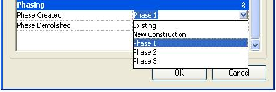
注意:在Revit中,创建轴网时,轴网将自动按数字或字母顺序命名。

阶段

一些建筑项目,如翻新,分阶段进行。阶段具有以下特征:

  • 阶段表示项目生命周期中的不同时间段。
  • 建筑物内图元的寿命由阶段控制。
  • 每个元素都有一个构造阶段,但只有具有有限寿命的元素才有一个破坏阶段。

项目中的所有阶段都可以从Document对象中检索。Phase对象包含三个有用的信息:Name、ID和UniqueId。其余属性始终返回null或空集合。

添加到项目中的每个新建模构件都具有“创建的阶段ID”和“拆除的阶段ID”特性。Element.AllowPhases()方法指示是否可以修改其阶段ID属性。

“创建的阶段ID”特性具有以下特征:

  • 它标识添加组件的阶段。
  • 默认值为与当前视图“阶段”值相同的ID。
  • 通过选择与下拉列表相对应的新值来更改“创建的阶段ID”参数。

已拆除阶段ID属性具有以下特征:

  • 它标识在哪个阶段拆除构件。
  • 默认值为无。
  • 使用拆除工具拆除构件会将特性更新为拆除图元所在视图中的当前阶段ID值。
  • 可以通过将“已拆除的阶段ID”特性设置为其他值来拆除构件。
  • 如果使用Revit Platform API删除某个阶段,则当前阶段中的所有建模构件仍然存在。这些元件的“创建的阶段ID”参数值将更改为“特性”对话框下拉列表中的下一项。 img

图65:阶段创建的组件参数值

下面的代码示例显示当前文档中支持的所有阶段。阶段名称显示在消息框中。

代码区域15-6:展示所有支持的阶段

1
2
3
4
5
6
7
8
9
10
11
12
13
14
15
16
17
18
19
20
21
void Getinfo_Phase(Document doc)
{
// Get the phase array which contains all the phases.
PhaseArray phases = doc.Phases;
// Format the string which identifies all supported phases in the current document.
String prompt = null;
if (0 != phases.Size)
{
prompt = "All the phases in current document list as follow:";
foreach (Phase ii in phases)
{
prompt += "\n\t" + ii.Name;
}
}
else
{
prompt = "There are no phases in current document.";
}
// Give the user the information.
TaskDialog.Show("Revit",prompt);
}

设计选项

设计选项提供了一种在项目中探索备选设计的方法。

设计选项提供了适应项目范围变化或开发供审查的替代设计的灵活性。您可以开始使用主项目模型,然后沿着向客户展示的方式开发变体。大多数图元都可以添加到设计选项中。不能添加到设计选项中的图元被视为主模型的一部分,并且没有设计备选方案。

设计选项的主要用途是作为元素类的属性。请参阅以下示例。

代码区域15-7:使用设计选项

1
2
3
4
5
6
7
8
9
10
11
12
13
14
15
16
void Getinfo_DesignOption(Document document)
{
// Get the selected Elements in the Active Document
UIDocument uidoc = new UIDocument(document);
ICollection selectedIds = uidoc.Selection.GetElementIds();

foreach (ElementId id in selectedIds)
{
Element element = document.GetElement(id);
//Use the DesignOption property of Element
if (element.DesignOption != null)
{
TaskDialog.Show("Revit",element.DesignOption.Name.ToString());
}
}
}

以下规则适用于设计选项

  • 如果元素位于主模型中,则DesignOption属性的值为null。否则,将返回在Revit UI中创建的名称。
  • ActiveDocument中只能存在一个活动DesignOption元素。
    • 主选项被视为默认的活动DesignOption。例如,一个设计选项集名为“墙”,该设计选项集中有两个设计选项,分别名为“砖墙”和“玻璃墙”。如果“砖墙”是主选项,则元素迭代器只检索此选项和属于它的元素。“玻璃墙”不活跃。

注:翻译自Revit API Developers Guide