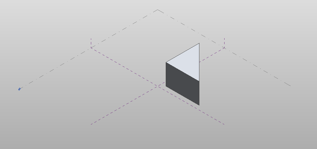
// Create one profile ReferenceArray ref_ar = new ReferenceArray();
XYZ ptA = new XYZ(0, 0, 10); XYZ ptB = new XYZ(100, 0, 10); Line line = Line.CreateBound(ptA, ptB); ModelCurve modelcurve = MakeLine(document, ptA, ptB); ref_ar.Append(modelcurve.GeometryCurve.Reference);
ptA = new XYZ(100, 0, 10); ptB = new XYZ(100, 100, 10); modelcurve = MakeLine(document, ptA, ptB); ref_ar.Append(modelcurve.GeometryCurve.Reference);
ptA = new XYZ(100, 100, 10); ptB = new XYZ(0, 0, 10); modelcurve = MakeLine(document, ptA, ptB); ref_ar.Append(modelcurve.GeometryCurve.Reference);
// Create axis for revolve form ptA = new XYZ(-5, 0, 10); ptB = new XYZ(-5, 10, 10); ModelCurve axis = MakeLine(document, ptA, ptB);
// make axis a Reference Line axis.ChangeToReferenceLine();
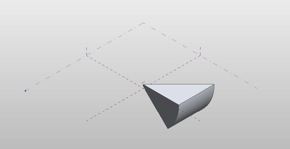
// Typically this operation produces only a single form, // but some combinations of arguments will create multiple froms from a single profile. revolveForms = document.FamilyCreate.NewRevolveForms(true, ref_ar, axis.GeometryCurve.Reference, 0, Math.PI / 4);
return revolveForms; }
public ModelCurve MakeLine(Document doc, XYZ ptA, XYZ ptB) { Autodesk.Revit.ApplicationServices.Application app = doc.Application; // Create plane by the points Line line = Line.CreateBound(ptA, ptB); XYZ norm = ptA.CrossProduct(ptB); if (norm.IsZeroLength()) norm = XYZ.BasisZ; Plane plane = Plane.CreateByNormalAndOrigin(norm, ptB); SketchPlane skplane = SketchPlane.Create(doc, plane); // Create line here ModelCurve modelcurve = doc.FamilyCreate.NewModelCurve(line, skplane); return modelcurve; }
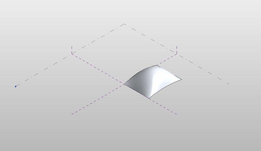
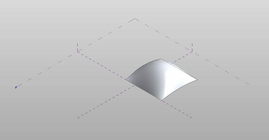
private Form CreateLoftForm(Autodesk.Revit.Document document) { Form loftForm = null;
ReferencePointArray rpa = new ReferencePointArray(); ReferenceArrayArray ref_ar_ar = new ReferenceArrayArray(); ReferenceArray ref_ar = new ReferenceArray(); ReferencePoint rp = null; XYZ xyz = null;
// make first profile curve for loft xyz = document.Application.Create.NewXYZ(0, 0, 0); rp = document.FamilyCreate.NewReferencePoint(xyz); rpa.Append(rp);
xyz = document.Application.Create.NewXYZ(0, 50, 10); rp = document.FamilyCreate.NewReferencePoint(xyz); rpa.Append(rp);
xyz = document.Application.Create.NewXYZ(0, 100, 0); rp = document.FamilyCreate.NewReferencePoint(xyz); rpa.Append(rp);
// make second profile curve for loft xyz = document.Application.Create.NewXYZ(50, 0, 0); rp = document.FamilyCreate.NewReferencePoint(xyz); rpa.Append(rp);
xyz = document.Application.Create.NewXYZ(50, 50, 30); rp = document.FamilyCreate.NewReferencePoint(xyz); rpa.Append(rp);
xyz = document.Application.Create.NewXYZ(50, 100, 0); rp = document.FamilyCreate.NewReferencePoint(xyz); rpa.Append(rp);
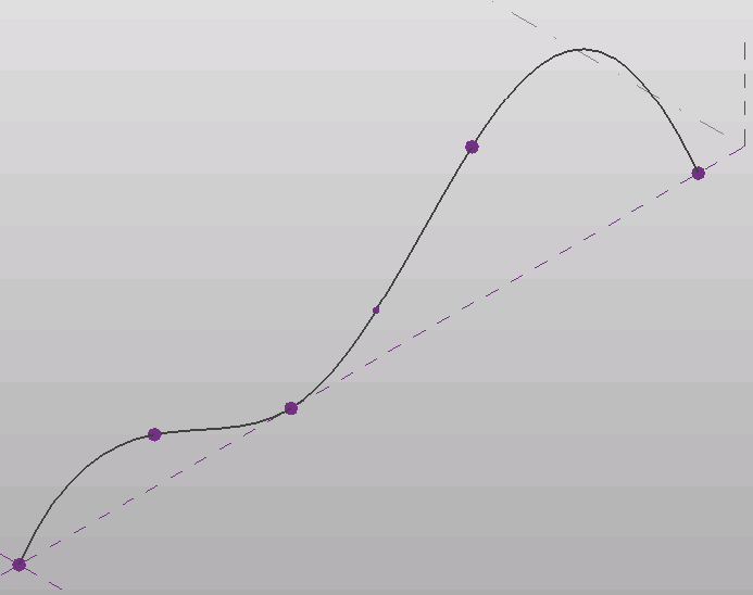
cbp = document.FamilyCreate.NewCurveByPoints(rpa); ref_ar.Append(cbp.GeometryCurve.Reference); ref_ar_ar.Append(ref_ar); rpa.Clear(); ref_ar = new ReferenceArray();
// make third profile curve for loft xyz = document.Application.Create.NewXYZ(75, 0, 0); rp = document.FamilyCreate.NewReferencePoint(xyz); rpa.Append(rp);
xyz = document.Application.Create.NewXYZ(75, 50, 5); rp = document.FamilyCreate.NewReferencePoint(xyz); rpa.Append(rp);
xyz = document.Application.Create.NewXYZ(75, 100, 0); rp = document.FamilyCreate.NewReferencePoint(xyz); rpa.Append(rp);
publicvoidMoveForm(Form form) { int profileCount = form.ProfileCount; if (form.ProfileCount > 0) { int profileIndex = 0; // modify the first form only if (form.CanManipulateProfile(profileIndex)) { XYZ offset = new XYZ(-25, 0, 0); form.MoveProfile(profileIndex, offset); } } }
publicvoidMoveSubElement(Form form) { if (form.ProfileCount > 0) { int profileIndex = 0; // get first profile ReferenceArray ra = form.get_CurveLoopReferencesOnProfile(profileIndex, 0); foreach (Reference r in ra) { ReferenceArray ra2 = form.GetControlPoints(r); foreach (Reference r2 in ra2) { Point vertex = document.GetElement(r2).GetGeometryObjectFromReference(r2) as Point;
XYZ offset = new XYZ(0, 15, 0); form.MoveSubElement(r2, offset); break; // just move the first point } } } }
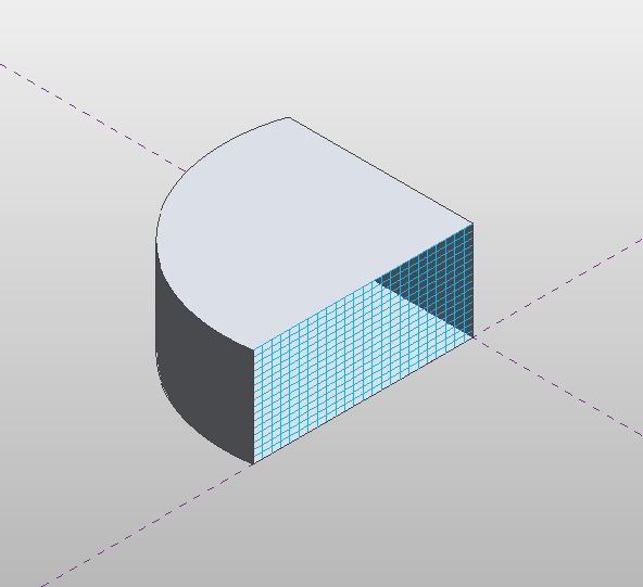
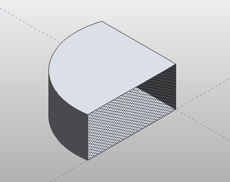
Autodesk.Revit.DB.GeometryElement geomElem = form.get_Geometry(opt); foreach (GeometryObject geomObj in geomElem) { Solid solid = geomObj as Solid; foreach (Face face in solid.Faces) { if (face.Reference != null) { DividedSurface ds = DividedSurface.Create(document,face.Reference); // create a divided surface with fixed number of U and V grid lines SpacingRule srU = ds.USpacingRule; srU.SetLayoutFixedNumber(16, SpacingRuleJustification.Center, 0, 0);
Family family = document.OwnerFamily; if (family.IsCurtainPanelFamily == true && family.CurtainPanelTilePattern == TilePatternsBuiltIn.Rectangle) { // first change spacing of grids in family document family.CurtainPanelHorizontalSpacing = 20; family.CurtainPanelVerticalSpacing = 30;
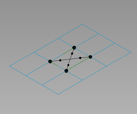
// create new points and lines on grid Autodesk.Revit.ApplicationServices.Application app = document.Application; FilteredElementCollector collector = new FilteredElementCollector(document); ICollection collection = collector.OfClass(typeof(ReferencePoint)).ToElements(); int ctr = 0; ReferencePoint rp0 = null, rp1 = null, rp2 = null, rp3 = null; foreach (Autodesk.Revit.DB.Element e in collection) { ReferencePoint rp = e as ReferencePoint; switch (ctr) { case0: rp0 = rp; break; case1: rp1 = rp; break; case2: rp2 = rp; break; case3: rp3 = rp; break; } ctr++; }
privatevoidCreateAdaptiveComponentInstance(Document document, FamilySymbol symbol) { // Create a new instance of an adaptive component family FamilyInstance instance = AdaptiveComponentInstanceUtils.CreateAdaptiveComponentInstance(document, symbol);
// Get the placement points of this instance var placePointIds = new List<ElementId>(); placePointIds = AdaptiveComponentInstanceUtils.GetInstancePlacementPointElementRefIds(instance).ToList(); double x = 0;
// Set the position of each placement point foreach (ElementId id in placePointIds) { ReferencePoint point = document.GetElement(id) as ReferencePoint; point.Position = new Autodesk.Revit.DB.XYZ(10*x, 10*Math.Cos(x), 0); x += Math.PI / 6; } }