
10视图
视图
视图是从 Revit 模型生成的图像,具有对文档中存储的数据的特权访问权限。它们可以是图形 (如计划) 或文本 (如计划)。每个项目文档都有一个或多个不同的视图。最后一个聚焦窗口是活动视图。
Autodesk.Revit.DB.View 类是 Revit 文档中所有视图类型的基类。Autodesk.Revit.UI.UIView 类表示 Revit 用户界面中的窗口视图。
在以下部分中,您将了解如何生成视图、Revit 支持的视图类型、每个视图的功能以及用户界面中视图窗口的可用功能。
Pages in this section 此部分中的页面
- About views 关于视图
- View Graphics 视图图形
- View Types 视图类型
- Revisions 修改
- View Filters 视图筛选器
- View Cropping 视图裁剪
- Displaced Views 置换视图
- UIView
关于视图
Revit API 提供对视图属性的访问,以及以编程方式创建和删除视图的功能。
本节是一个高级概述,其中包括以下内容:
- 视图是如何生成的
- 视图类型
- 查看导航工具
- 创建和删除视图。
视图的生成
下图说明了视图是如何生成的。
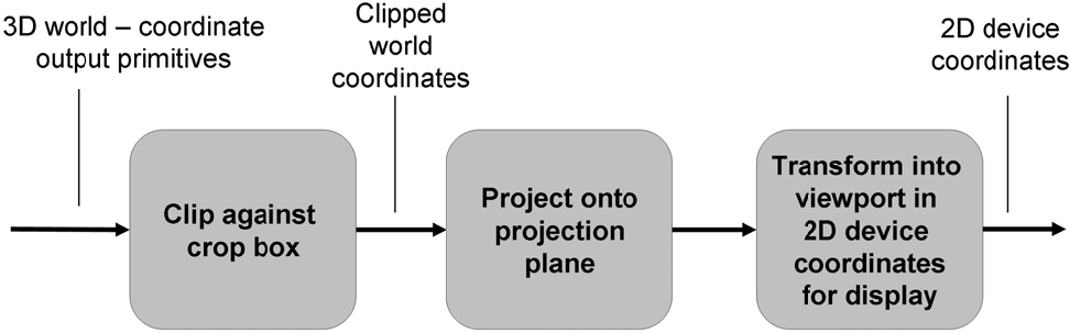
图 94: 创建视图过程
每个视图都是通过将三维对象投影到二维投影平面上来生成的。投影分为两个基本类:
- Perspective 透视
- Parallel 平行
确定投影类型后,必须指定需要 3D 模型和渲染场景的条件。有关投影的更多信息,请参阅 View3D 部分。
世界坐标包括以下内容:
- 观看者的眼睛位置
- 显示投影的视图平面位置。
Revit 使用两个坐标系:
- 建筑所在的全局空间或模型空间坐标
- 视图坐标系。
视图坐标系表示模型在观察者视图中的呈现方式。它的原点是查看者的眼睛位置,其在模型空间中的坐标由View.Origin属性检索。X、Y和Z轴分别由View.RightDirection、View.UpDirection和View.ViewDirection属性表示。
- View.RightDirection 朝向屏幕右侧。
- View.UpDirection 朝向屏幕的上方。
- View.ViewDirection 从屏幕到观察者的方向。
视图坐标系是右手坐标系。有关详细信息,请参见View3D和View3D中的平行投影图片。
在投影到投影平面上之前,将排除3D模型空间中不显示的某些部分,例如位于查看器后面或距离太远而无法清晰显示的部分。此操作需要裁剪视图。以下规则适用于裁剪:
- Elements outside of the crop region are no longer in the view.
裁剪区域之外的图元将不再位于视图中。 - View.GetCropRegionShapeManager方法返回ViewCropRegionShapeManager,它提供裁剪区域的边界信息,裁剪区域可以是矩形,也可以不是矩形。
- View.CropBoxVisible属性确定裁剪框在视图中是否可见。
- View.CropBoxActive属性确定裁剪框是否实际用于裁剪视图。
裁剪后,模型将投影到投影平面上。以下规则适用于投影:
- 投影内容映射到屏幕视图端口进行显示。
- 在映射过程中,投影内容会被缩放,以便在屏幕上正确显示。
- View.Scale属性是实际模型大小与视图大小的比率。
- 图纸上的视图边界是裁剪区域,它是裁剪形状在投影平面上的投影。
- 裁剪区域的大小和位置由View.Outline属性确定。
视图导航工具
您可以访问有关当前在View Cube设置中设置的主视图摄影机的信息。文档只能设置一个主视图摄像机。这对应于用户调用ViewCube UI命令以在ViewCube右键单击关联菜单中“将当前视图设置为主视图”时保存的视图方向和其他摄影机参数。
通过调用静态方法ViewNavigationToolSettings.GetViewNavigationToolSettings()访问ViewNavigationToolSettings,该方法将返回与文档关联的ViewNavigationToolSettings元素。
ViewNavigationToolSettings将允许您查询是否已使用IsHomeCameraSet()方法设置主视图,该方法返回指示主视图设置的当前状态的布尔值。
通过使用ViewNavigationToolSettings.GetHomeCamera()方法获取主摄影机的副本,可以访问有关在ViewCube中设置的主摄影机的只读信息。如果HomeCamera尚未设置,则此函数返回“否”。HomeCamera类提供有关相机和模型中存储的主视图方向(如EyePosition和UpDirection)的视图的信息。
创建和删除视图
Revit Platform API提供了多种方法来创建从Autodesk.Revit.DB.View类派生的相应视图图元。大多数视图类型都是使用派生视图类的静态方法创建的。如果视图创建成功,这些方法返回对视图的引用,否则返回null。在下面的部分中,将针对每个视图类描述这些方法。
也可以使用View.Duplicate()方法创建视图。可以从现有视图创建新视图,并可以选择新视图是从属视图还是具有详图。以下示例演示如何创建新的依赖视图。
代码区域:创建依赖视图
1 | public View CreateDependentCopy(View view) |
使用Document.Delete()方法和视图ID删除视图。您还可以删除与视图关联的元素。例如,删除标高图元会导致Revit删除相应的平面视图,或删除相机图元会导致Revit删除相应的三维视图。
依赖视图 如上所述,可以使用View.Duplicate()方法并传入ViewDuplicationOption枚举器的AsDependent值来创建依赖视图。从属视图将与主视图和所有其他从属视图保持同步,以便在一个视图中进行视图特定更改(如视图比例和注释)时,这些更改将反映在所有视图中。并非所有视图类型都可以复制,并且不能从另一个从属视图创建从属视图。使用View.CanViewBeDuplicated()确保可以从视图生成依赖视图。此方法采用ViewDuplicationOption枚举来检查是否可以以特定方式复制视图。可以将视图复制为独立视图,但不能复制为从属视图。 从属视图具有有效的主视图元素ID,可以从方法View.GetPrimaryViewId()获得该ID。独立视图的主视图ID为InvalidElementId。可以使用View.ConvertToIndependent()方法将依赖视图转换为独立视图。如果视图不是依赖的,这个方法将抛出一个异常。
代码区域:使依赖视图独立
1 | public void MakeViewIndependent(View view) |
视图图形
视图的许多图形元素和显示选项都是通过API公开的。
视图类具有用于获取和设置显示样式设置和详细程度设置的属性。View. DisplayStyle属性使用DisplayStyle枚举,并与Revit窗口底部可用的显示选项相对应,如下所示。
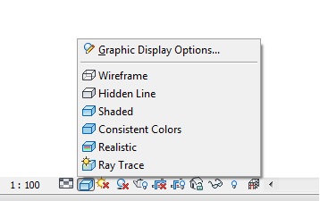
注意:不能从Revit AP将显示样式设置为光线跟踪,因为此显示样式会将Revit置于功能有限的受限模式。View. DetailLevel属性使用ViewDetailLevel枚举,并对应于Revit窗口底部可用的详细程度选项,如下所示。
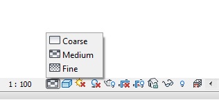
ViewDetailLevel枚举在给定View不使用详细级别的情况下包含Undefined。
Thin Lines 细线
“细线”选项(在Revit UI的“视图”选项卡的“图形”面板上可用)控制如何在视图中绘制线。通常,在小比例视图中放大模型时,元素线看起来比实际粗得多。启用“细线”时,无论缩放级别如何,所有线条都将绘制为单一宽度。此选项通过ThinLinesOptions实用程序类提供,该类具有一个名为AreThinLinesEnabled的属性。它是影响整个Revit任务的静态属性。
临时视图模式
TemporaryViewModes类允许控制临时视图模式。可以从View.TemporaryViewModes属性访问它。对于不支持临时视图模式的视图,此属性将为空。RevealConstraints、RevealHiddenElements和WorksharingDisplay属性可用于获取和设置相应视图中这些模式的当前状态。请注意,某些模式仅在某些视图和/或特定上下文中可用。另外,在当前上下文中不一定启用可用模式。TemporaryViewModes方法IsModeAvailable()和IsModeEnabled()可用于测试特定模式在使用前是否可用和启用。这些方法采用TemporaryViewMode枚举。可能的选项如下所示。
| Member Name 成员名称 | Description 描述 |
|---|---|
| RevealHiddenElements | 显示隐藏元素模式 |
| TemporaryHideIsolate | 临时隐藏/隔离模式 |
| WorksharingDisplay | 工作共享显示模式 |
| TemporaryViewProperties | 临时视图属性模式 |
| Raytrace | 在交互式光线跟踪中显示模型的模式 |
| ExplodedView | 以分解视图显示模型并允许用户更改/配置的模式 |
| RevealConstraints | 显示模型中元素之间约束的模式 |
代码区域:显示视图中的隐藏元素
1 | public bool RevealHiddenElementsInView(View view) |
IsModeActive()方法测试给定的模式当前是否在视图中处于活动状态。使用DeactivateAllModes()方法停用所有当前活动的视图,或使用DeactiveMode()停用特定模式。 PreviewFamilyVisibility属性获取和设置关联视图中PreviewFamilyVisibility模式的当前状态。仅当视图的文档位于族编辑器的环境中时,此模式才可用。此属性是PreviewFamilyVisibilityMode枚举值而不是bool。此模式的可能状态为:
| **Member Name ** | Description |
|---|---|
| Off | 未应用图元可见性。所有族元素均可见。 |
| On | 视图的图元可见性应用于仅显示可见图元。由参照平面剪切的图元将显示其各自的剪切几何图元。 |
| Uncut | 视图的图元可见性应用于在实例未被剪切时显示可见的图元。请注意,此状态仅在某些视图(如楼层平面和天花板)中可用。 |
即使视图的PreviewFamilyVisibility模式可用并已启用,也并非所有状态在所有视图中都有效。在将这些状态之一应用于视图之前,调用IsValidState()以确保可以应用它。
代码区域:关闭预览族可见性模式
1 | public void TurnOffFamilyVisibilityMode(View view) |
首次打开视图时,其PreviewFamilyVisibility模式的状态将根据默认设置确定,该默认设置通过静态TemporaryViewModes属性PreviewFamilyVisibilityDefaultOnState和PreviewFamilyVisibilityDefaultUncutState进行控制,如下所示。
代码区域:设置默认预览族可见性状态
1 | public void SetDefaultPreviewFamilyVisibilityState() |
PreviewFamilyVisibilityDefaultOnState值控制是否默认打开每个新打开的视图的PreviewFamilyVisibility模式。此属性适用于所有类型的视图。同时支持剪切和未剪切预览的视图(如楼层平面)将使用由PreviewFamilyVisibilityDefaultUncutState属性指示的剪切/未剪切状态,但前提是PreviewFamilyVisibilityDefaultOnState属性设置为true。 这些设置适用于整个应用程序,而不是单个族文档;这些值在Revit任务之间保持不变。尽管允许随时设置该值,但在Revit应用程序初始化后所做的任何更改在下一个Revit任务之前都不会生效。 请注意,一旦显式修改PreviewFamilyVisibility属性,即使在关闭视图并稍后再次重新打开之后,应用的设置也会对相应视图保持有效。
视图中元素可见性
视图跟踪可见元素。所有在视图中可见的图形化元素都可以使用FilteredElementCollector进行检索,该Collector是用文档和视图的id构造的。然而,集合中的某些元素可能被其他元素隐藏或覆盖。可以通过旋转视图或移除覆盖它们的图元来查看它们。删除这些可见图元可能需要Revit重新生成视图的几何图形。当您的代码第一次为给定视图使用此构造函数时,或者当您的代码第一次为显示设置刚刚更改的视图使用此构造函数时,您可能会遇到显著的性能下降。 可以在特定视图中隐藏单个图元。方法Element.IsHidden()指示元素是否在给定视图中隐藏,Element.CanBeHidden()返回元素是否可以隐藏。要隐藏单个元素,请使用View.HideElements(),它接受与要隐藏的元素相对应的ElementId集合。 元素可见性也可以按类别更改。 GetCategoryHidden()方法查询类别ID以确定它在视图中是隐藏还是可见。 方法的作用是:将特定类别中的所有元素设置为隐藏或可见。 * CanCategoryBeHidden()方法指示是否可以在视图中隐藏特定类别的元素。 基于视图的FilteredElementCollector将仅包含当前视图中可见的元素。不能检索非图形元素或不可见元素。基于文档的FilteredElementCollector检索文档中的所有元素,包括不可见元素和非图形元素。例如,在空项目中创建默认三维视图时,视图中没有元素,但文档中有许多元素,所有这些元素都不可见。 下面的代码示例计算活动文档和活动视图中墙类别元素的数量。活动视图中的元素数量与文档中的元素数量不同,因为文档包含非图形墙类别元素。
代码区域:计算活动视图中的元素
1 | private void CountElements(UIDocument uiDoc) |
临时视图模式会影响图元的可见性。IsInTemporaryViewMode()方法可用于确定View是否处于临时视图模式。方法View.IsElementVisibleInTemporaryViewMode()标识元素在指定的视图模式中是否应可见。这仅适用于TemporaryHideIsolate和AnalyticalModel视图模式。其他模式将导致异常。
深度提示 ViewDisplayDepthCueing类提供了对剖面视图和立面视图中远处对象显示的控制。当景深效果处于活动状态时,随着与观察者距离的增加,对象会融入背景色(淡入淡出)。可以使用View.GetDepthCueing()检索视图的当前深度提示设置。如果对返回的ViewDisplayDepthCueing进行了更改,则在调用View.SetDepthCueing()之前,这些更改不会应用于视图。 ViewDisplayDepthCueing类具有以下属性:
| Member Name 成员名称 | Description 描述 |
|---|---|
| EnableDepthCueing | 为True,则启用深度提示。 |
| StartPercentage | 指示深度提示开始的位置。值为0表示深度提示从视图的前剪辑平面开始。 |
| EndPercentage | 指示深度提示结束的位置。比结束平面更远的对象将与结束平面处的对象淡入淡出相同的量。值100表示远剪裁平面。 |
| FadeTo | 指示通过深度提示淡入淡出对象的最大量。值为100表示完全不可见。 |
SetStartEndPerception()方法可用于在一次调用中设置开始和结束百分比。 下面的示例演示如何获取当前深度提示、更改其属性并将其设置回视图。请注意,并非所有视图都可以使用深度提示。
代码区域:更改视图的深度提示
1 | private void AdjustDepthCueing(View view) |
视图类型
不同类型的Revit视图由Revit API中的不同类表示。有关每种视图类型的详细信息,请参阅以下主题。
本节中的页面
- 概述
- 3D视图
- 视图平面
- 视图图纸
- 剖面图
- 图纸
- 图表
概述
一个项目模型可以有几种视图类型。在API中,有三种方法对视图进行分类。第一种方法是使用视图元素View.ViewType属性。它返回指示视图类型的枚举值。下表列出了所有可用的视图类型。
表44:Autodesk.Revit.DB.ViewType
| Member Name 成员名称 | Description 描述 |
|---|---|
| AreaPlan | 区域视图。 |
| CeilingPlan | 天花板反射平面图。 |
| ColumnSchedule | 柱表视图。 |
| CostReport | 成本报告视图。 |
| Detail | 局部视图。 |
| DraftingView | 草图视图。 |
| DrawingSheet | 图纸工作表。 |
| Elevation | 立面视图。 |
| EngineeringPlan | 工程视图。 |
| FloorPlan | 楼层平面视图。 |
| Internal | Revit的内部视图。 |
| Legend | 图例视图。 |
| LoadsReport | 荷载报告视图。 |
| PanelSchedule | 配电盘明细表视图。 |
| PressureLossReport | 压力损失报告视图。 |
| Rendering | 渲染视图。 |
| Report | 报告视图。 |
| Schedule | 视图表。 |
| Section | 剖面视图。 |
| ThreeD | 3D视图。 |
| Undefined | 未定义/未指定视图。 |
| Walkthrough | Walkthrough视图。 |
分类视图的第二种方法是按类类型。下表列出了项目浏览器中的视图类型和相应视图。
表45:项目浏览器视图
| Project Browser Views 项目浏览器视图 | View Type 视图类型 | Class Type 类类型 |
|---|---|---|
| Area Plans | ViewType.AreaPlan | Elements.ViewPlan |
| Ceiling Plans | ViewType.CeilingPlan | Elements.ViewPlan |
| Graphic Column Schedule | ViewType.ColumnSchedule | Elements.View |
| Detail Views | ViewType.Detail | Elements.ViewSection |
| Drafting Views | ViewType.DraftingView | Elements.ViewDrafting |
| Sheets | ViewType.DrawingSheet | Elements.ViewSheet |
| Elevations | ViewType.Elevation | Elements.ViewSection |
| Structural Plans | ViewType.EngineeringPlan | Elements.ViewPlan |
| Floor Plans | ViewType.FloorPlan | Elements.ViewPlan |
| Legends | ViewType.Legend | Elements.View |
| Reports (MEP engineering) | ViewType.LoadsReport | Elements.View |
| Reports (MEP engineering) | ViewType.PanelSchedule | Elements.PanelScheduleView |
| Reports (MEP engineering) | ViewType.PresureLossReport | Elements.View |
| Renderings | ViewType.Rendering | Elements.ViewDrafting |
| Reports | ViewType.Report | Elements.View |
| Schedules/Quantities | ViewType.Schedule | Elements.ViewSchedule |
| Sections | ViewType.Section | Elements.ViewSection |
| 3D Views | ViewType.ThreeD | Elements.View3D |
| Walkthroughs | ViewType.Walkthrough | Elements.View3D |
此示例说明如何使用视图的ViewType属性来确定视图的类型。
代码区域:确定视图类型
1 | public void GetViewType(Autodesk.Revit.DB.View view) |
分类视图的第三种方法是使用ViewFamilyType类。大多数视图创建方法需要新视图的ViewFamilyType的ID。可以从View.GetTypeId()方法中检索ViewFamilyType的ID。ViewFamily属性返回ViewFamily枚举,它指定ViewFamilyType的族,类似于上面记录的ViewType枚举。下面的示例说明如何从View获取ViewFamily。
代码区域:从ViewFamilyType确定视图类型
1 | public ViewFamily GetViewFamily(Document doc, View view) |
3D视图
View3D是一个自由导向的三维视图。
有两种三维视图:透视视图和等轴测视图,在Revit用户界面中也称为正交视图。差异基于投影射线关系。View3D.IsPerspective属性指示三维视图是透视视图还是等轴测视图。
透视图
下图说明了如何创建透视图。
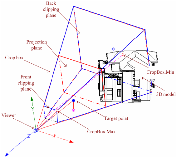
图96:透视投影
- 直投影射线穿过模型中的每个点并与投影平面相交以形成投影内容。
- 为了便于从世界坐标到视图平面的变换,视图坐标系基于观察者。
- 它的原点由View.Origin属性表示,是查看者的位置。
- 使用ViewOrientation3D.EyePosition属性(从View3D.GetOrientation()检索)检索查看器的世界坐标。因此,在3D视图中,View.Origin始终等于相应的ViewOrientation3D.EyePosition。
- 如上图所述,观察坐标系确定如下:
- X轴由View.RightDirection确定。
- Y轴由View.UpDirection确定。
- Z轴由View.ViewDirection确定。
- 观看方向是在3D空间中从目标点到观看者,以及在屏幕空间中从屏幕到观看者。
静态方法View3D.ViewPerspective()方法可用于创建新的透视图。
代码区域:View3D.CreatePerspective()
1 | public static View3D View3D.CreatePerspective (Document document, ElementId viewFamilyTypeId; |
viewFamilyTypeId参数必须是三维ViewType。 下面的代码示例说明如何创建透视三维视图。
代码区域:创建透视三维视图
1 | // Find a 3D view type |
透视视图裁剪框是锥体的一部分,其顶点位于查看者位置。它是两个平行剪裁平面之间的几何体。裁剪框限定模型中被裁剪并投影到视图平面上的部分。 裁剪框由View.CropBox属性表示,该属性返回一个BoundingBoxXYZ对象。 CropBox.Min和CropBox.Max点在上一张图片中标记。请注意,透视图中的CropBox.Min点是通过将裁剪框前裁剪平面投影到后裁剪平面上而生成的。 裁剪框坐标基于查看坐标系。使用Transform.OfPoint()将CropBox.Min和CropBox.Max变换到世界坐标系。有关变换的更多详细信息,请参见几何部分中的几何辅助类。 投影平面加上前剪裁平面和后剪裁平面都垂直于视图方向。CropBox.Max和CropBox.Min之间的线与查看方向平行。利用这些因子,可以计算裁剪框几何形状。
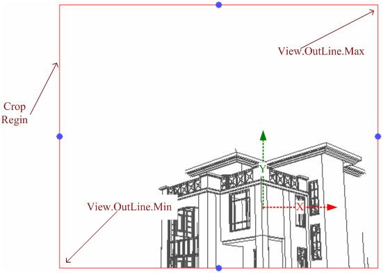
图97:透视3D视图
上图显示了裁剪后屏幕上的投影平面。裁剪区域是投影平面和裁剪框的矩形相交。 使用View.CropRegion属性检索几何信息。此属性返回BoundingBoxUV实例。 View.Outline.Max属性指向右上角。 View.Outline.Min属性指向左下角。 与裁剪框类似,裁剪区域坐标基于查看坐标系。下列表达式是相等的。
1 | View.CropBox.Max.X(Y) / View.OutLine.Max.X(Y) == View.CropBox.Min.X(Y) / View.OutLine.Min.X(Y) |
由于物体的透视投影的大小与从该物体到投影中心的距离成反比,因此比例对于透视图来说是没有意义的。透视三维视图的“比例”属性始终返回零。 #管理摄像头目标 相机表示透视视图的查看者正在查看的方向。如果用户或API应用调整裁剪区域以暴露更宽的视场或不对称的视场,则透视图的失真可能变得过于剧烈。可以通过调用View3D方法RestCameraTarget()将摄像机目标定位在视场的中心,从而将摄像机目标强制定位到观察区域的中心。在调用之前,请检查是否可以使用View3D.CanResetCameraTarget()方法在此视图中重置摄像机,该方法指示是否可以重置摄像机目标。无法重置目标的主要情况是View3D当前处于等轴测投影中。尝试在等轴测视图中重置相机目标将引发Autodesk. Revit. Exceptions. InvalidOperationException。
等距视图 可以使用静态View3D.NETIsometric()方法创建新的等轴测视图。
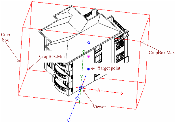
图98:平行投影
等轴测视图是使用平行投影光线通过将模型投影到与光线垂直的平面上而生成的。查看坐标系类似于透视图,但裁剪框是一个平行六面体,其面与投影光线平行或垂直。View.CropBox属性指向两个对角,其坐标基于查看坐标系。
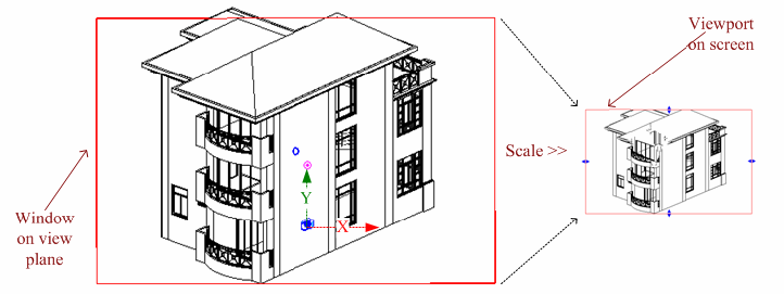
图99:将视图平面上的窗口缩放到屏幕视口
模型将投影到视图平面上,然后缩放到屏幕上。View.Scale属性表示实际模型大小与视图大小的比率。相关表达式如下:
1 | View.CropBox.Max.X(Y) / View.OutLine.Max.X(Y) == View.CropBox.Min.X(Y) / View.OutLine.Min.X(Y) == View.Scale |
代码区域:View3D.Other Isometric()
1 | public static View3D View3D.CreateIsometric (Document document, ElementId viewFamilyTypeId; |
viewFamilyTypeId参数必须是三维ViewType。Revit确定以下内容:观察者的位置。 如何使用视图方向创建视图坐标系。 * 如何创建裁剪框来裁剪模型。 创建视图后,可以调整裁剪框的大小以查看模型的不同部分。也可以更改默认方向。API不支持修改查看坐标系。 下面的代码示例说明如何创建等轴测三维视图。
1 | // Find a 3D view type |
在等距和透视之间切换
大多数情况下,View3D可以在“等轴测”和“透视”之间切换,前提是视图中没有视图特定的元素。View3D类提供了在等轴测和透视模式之间切换视图的方法。在切换之前,使用CanToggleBetweenPerspectiveAndIsometric()方法,该方法指示是否可以进行切换。
要切换视图,请调用以下两个View 3D类方法之一:ToggleToPerspective()或ToggleToIsometric()。如果无法切换视图(可能是由于视图中存在特定于视图的元素),则这两种方法中的任何一种都将引发Autodesk. Revit. Exceptions. InvalidOperationException。
3D视图剖面框
每个视图都有一个裁剪框。裁剪框聚焦于要投影并显示在视图中的模型部分。对于三维视图,还有另一个名为剖面框的框。
- 剖面框确定在三维视图中显示的模型部分。
- 剖面框用于剪裁三维模型的可见部分。
- 即使在裁剪框中,框外的部分也不可见。
- 剖面框与裁剪框的不同之处在于,剖面框可以随模型一起旋转和移动。
剖面框对于大型模型特别有用。例如,如果要渲染大型建筑,请使用剖面框。剖面框限制用于计算的模型部分。若要显示剖面框,请在“三维视图图元属性”对话框的“范围”区域中选择“剖面框”。也可以使用IsSectionBoxActive属性设置它。在下面的示例中,如果活动视图是三维视图,它将设置剖面框是否处于活动状态。
代码区域:显示/隐藏剖面框
1 | private void ShowHideSectionBox(UIDocument document, bool active) |
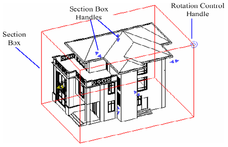
图100:剖面框
View3D.GetSectionBox()和View3D.SetSectionBox()方法用于获取和更改长方体范围。在某些情况下,调用View3D.SetSectionBox()可能会产生副作用。将该属性设置为某些值可以更改框的容量并将其显示在视图中。若要避免显示剖面框,请将IsSectionBoxActive属性设置为false。 下面的代码示例阐释如何更改剖面框的范围。
1 | private void ExpandSectionBox(View3D view) |
从GetSectionBox()方法返回的BoundingBoxXYZ的Max和Min点的坐标不是全局坐标。要将Max和Min的坐标转换为全局坐标,需要通过从BoundingBoxXYZ.Transform属性获得的变换来转换每个点。
代码区域:将最大值和最小值转换为全局坐标
1 | private void ConvertMaxMinToGlobal(View3D view, out XYZ max, out XYZ min) |
视图锁定
View3D类具有与Revit用户界面中可用的锁定功能相对应的方法和属性。

View3D.SaveOrientationAndLock()方法将保存方向并锁定视图,而View3D.RestoreOrientationAndLock()将恢复视图的方向并锁定它。View3D.RestoreOrientationAndLock()将解锁当前锁定的视图。IsLocked属性将返回3D视图当前是否被锁定。
视图平面
平面视图是基于标高的。平面视图有三种类型:楼层平面视图、天花板平面视图和面积平面视图。
创建平面视图
- 通常,楼层平面视图是在新项目中打开的默认视图。
- 大多数项目至少包括一个楼层平面视图和一个天花板平面视图。
- 通常在向项目中添加新标高后创建平面视图。
使用API添加新标高不会自动添加平面视图。使用静态ViewPlan.Create()方法创建新的地板和天花板平面视图。使用静态ViewPlan. ViewAreaPlan()方法创建新的面积平面视图。
代码区域:创建平面视图
1 | public static ViewPlan ViewPlan.Create(Document document, ElementId viewFamilyTypeId, ElementId levelId); |
ViewPlan.Create()中的viewFamilyTypeId参数必须是FloorPlan、CeilingPlan、AreaPlan或StructuralPlan ViewType。levelId参数表示与平面视图关联的项目中标高图元的ID。 下面的代码基于某个标高创建楼层平面和天花板平面。
代码区域:创建楼层平面和天花板平面
1 | private void CreateViewPlan(Autodesk.Revit.DB.Document document) |
平面视图属性
创建新平面视图后,可以使用类型为ViewDiscipline的Discipline参数设置视图的Discipline。选项包括建筑、结构、机械、电气、管道和协调。
对于结构平面视图,可以使用ViewFamilyType.PlanViewDirection属性将视图方向设置为“向上”或“向下”。尽管它是ViewFamilyType类的属性,但如果为StructuralPlan视图以外的视图访问该属性,则将引发异常。
视图范围
可以通过ViewPlan.GetViewRange()方法检索平面视图的视图范围。返回的PlanViewRange对象可用于查找平面相对的标高以及每个平面与该标高的偏移量。该信息与Revit用户界面的“视图范围”对话框中提供的信息相同:
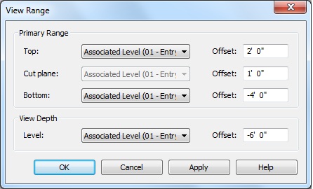
以下示例显示如何获取平面视图的顶部剪裁平面和关联偏移
代码区域:获取视图范围的信息
1 | private void ViewRange(Document doc, View view) |
平面图underlay
可以从ViewPlan中检索和设置顶层和底层范围。使用GetUnderlayBaseLevel()和SetUnderlayBaseLevel()访问对象范围的基准标高。如果基本级别ID为InvalidElementId,则不设置无效基本级别,并且没有元素显示为无效。设置参考底图范围的基准标高时,下一个最高标高的高程将用于确定参考底图范围的顶部。如果为基准标高指定的标高是最高标高,则该范围将是无边界的,并且将由指定标高以上的所有内容组成。
使用GetUnderlayTopLevel()和SetUnderlayRange()访问对象范围的顶级。如果GetUnderlayTopLevel()返回InvalidElementId,并且XML基础级别是有效级别,则XML范围是无边界的,并且包含XML基础级别之上的所有内容。若要设置顶层,必须使用SetUnderlayRange(),该方法将ElementIds用于底层和顶层。如果顶层的高程不大于底层的高程,此方法将引发异常。
使用GetUnderlayOrientation()和SetUnderlayOrientation()方法控制如何查看视图中的元素。UnderlayOrientation可以是LookingDown(向下查看图元,就像从上面向下查看一样)或LookingUp(向上查看图元,就像从下面向上查看一样)。
如果当前方向为LookingDown且顶级Id与新值不同,则以下代码设置范围。然后方向更改为LookingUp。
代码区域:更改视图范围
1 | private void ViewUnderlay(ViewPlan planView, ElementId topLevelId, ElementId baseLevelId) |
视图图纸
视图,用于创建不属于建模设计的、不关联的视图专有详图。
图纸视图未与模型关联。它允许用户创建不包括在模型中的详图。
在绘图视图中,用户可以以不同的视图比例(粗略、精细或中等)创建详图。
您可以使用2D详图工具,包括:
Detail lines Detail regions Detail components Insulation 详图线详图区域详图构件隔热层 Reference planes Dimensions Symbols Text 参照平面尺寸符号文字 这些工具与用于创建局部视图的工具相同。
图纸视图不显示模型图元。
使用静态ViewDrafting.Create()方法创建图纸视图。模型图元不显示在图纸视图中。
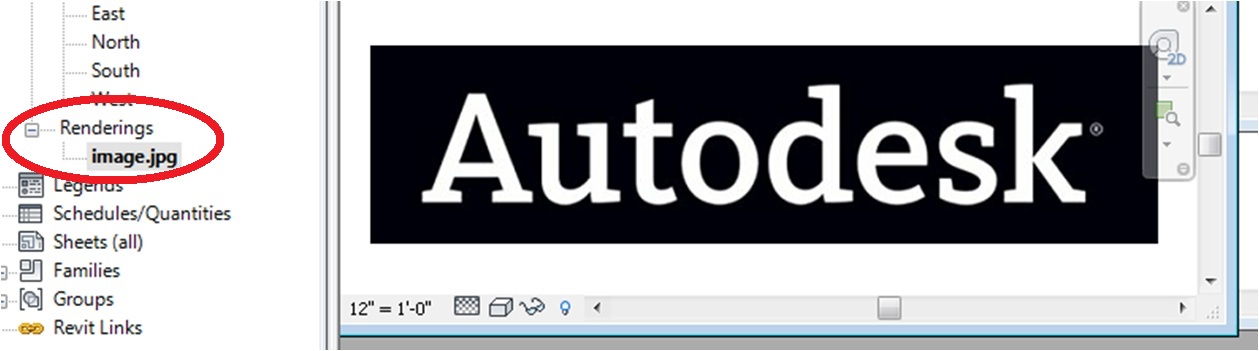
图片视图
ImageView类派生自ViewDrafting。它可用于创建包含从磁盘导入的图像的渲染视图。使用静态ImageView.Create()方法创建新的呈现视图。
剖面视图
表示剖面视图、局部视图、俯视图和立面视图,以及参照详图索引和参照剖面。
ViewSection类可用于创建剖面视图、局部视图、局部视图、参照详图索引和参照剖面。它还表示立面视图。
剖面视图和参照剖面
剖面视图剖切模型以显示内部结构。ViewSection.ViewSection()方法创建剖面视图。
代码区域:ViewSection. ViewSection()
1 | public ViewSection ViewSection.CreateSection(Document document, ElementId viewFamilyTypeId, BoundingBoxXYZ sectionBox); |
viewFamilyTypeId参数是新ViewSection将使用的ViewFamilyType的ID。类型必须是截面视图族。sectionBox参数是剖面视图裁剪框。它提供剖面视图所需的方向和范围。通常,另一个视图的裁剪框用作参数。您还可以构建自定义BoundingBoxXYZ实例来表示方向和范围。 下面的代码演示如何创建剖面视图。将在墙的中心创建剖面视图的边界框。生成的剖面视图将位于项目浏览器的“剖面(建筑剖面)”节点中。请注意,远裁剪距离将等于创建时边界框的最小值和最大值的z坐标之差。
代码区域:创建剖面图
1 | // Find a section view type |
参照剖面是参照现有视图的剖面。创建新参照剖面时,Revit不会添加新视图。
代码区域:ViewSection. ViewReferenceSection()
1 | public ViewSection ViewSection.CreateReferenceSection(Document document, |
parentViewId参数是将在其中显示新引用截面标记的视图的ID。可以在“楼层平面”、“天花板平面”、“结构平面”、“剖面”、“立面”、“绘图”和“详图”视图中创建参照剖面。viewIdToReference可以是详图、绘图或剖面视图的ID。新参照截面将使用参照视图的ViewFamilyType。这两个XYZ点将确定父视图中截面标记标头的位置。 #详细视图 局部视图是模型的视图,在其他视图中显示为剖面或截面。这种类型的视图通常以比父视图中更精细的细节比例来表示模型。它用于向模型的特定部分添加更多信息。静态ViewSection. ViewDetail()方法用于创建新的细节ViewSection。
代码区域:ViewSection. ViewDetail()
1 | public ViewSection ViewSection.CreateDetail(Document document, ElementId viewFamilyTypeId, BoundingBoxXYZ sectionBox); |
viewFamilyTypeId参数是新ViewSection将使用的ViewFamilyType的ID。类型必须是详图视图族。与标准剖面视图一样,sectionBox参数是剖面视图裁剪框。它提供剖面视图所需的方向和范围。 添加新详图ViewSection后,它将显示在项目浏览器的“详图视图(Detail)”节点中。 #立面视图 立面视图是模型的横截面,其中显示标高线。立面视图由ViewSection类表示。但是,与其他类型的横断面图不同,不能使用ViewSection类的静态方法创建立面视图。要创建立面视图,请先创建立面标记,然后使用该标记生成立面视图。新创建的立面视图将显示在项目浏览器的“立面(建筑立面)”节点中。它将被分配一个唯一的名称。 以下示例基于梁的位置创建立面视图。
代码区域:创建立面视图
1 | ViewSection CreateElevationView(Document document, FamilyInstance beam) |
ElevationMarker. Elevation()方法将ViewPlan的id作为参数。这是ElevationMarker可见的ViewPlan。新的立面ViewSection将从ViewPlan中导出其范围并继承设置。最后一个参数是将放置新立面视图的ElevationMarker上的索引。ElevationMarker上的索引必须有效且未使用。视图的方向由索引决定。 #标注和参考标注 视图以较大比例显示另一个视图的一部分。可以使用静态方法ViewSection. callout()创建标注视图。详图索引可以在“楼层平面”、“天花板平面”、“结构平面”、“剖面”、“立面”、“绘图”和“详图”视图中创建。生成的视图将是ViewSection、ViewPlan或ViewDetail,具体取决于所使用的ViewFamilyType,并将显示在项目浏览器的相应节点中。
代码区域:ViewSection. callout()
1 | public ViewSection ViewSection.CreateCallout(Document document, |
父视图ID参数可以是可在其上创建详图索引的任何类型的视图的ID。点参数确定父视图中的图元符号的范围。参照图元是指引用现有视图的图元。添加参照视图时,Revit不会在项目中创建视图。相反,它创建一个指向指定的现有视图的指针。多个参照详图索引可以指向同一视图。
代码区域:ViewSection. ViewReferenceCallout()
1 | public ViewSection ViewSection.CreateReferenceCallout(Document document, |
创建引用对象与创建对象类似。但是,与其将视图的ViewFamilyType的Id作为参数,还不如将视图ReferenceCallout()方法作为要引用的视图的Id。被引用视图的ViewFamilyType将由新引用对象使用。 只能参照裁剪的视图,除非参照的视图是“绘图”视图。无论父视图类型如何,始终可以参照绘图视图。立面视图可以从立面父视图和图纸父视图中参照。可以从“截面”和“绘图”父视图中参照截面视图。可以从所有父视图中参照详图视图,但在FloorPlan、CeilingPlan和StructuralPlan父视图中除外,在这些父视图中只能参照水平方向的详图视图。FloorPlan、CeilingPlan和StructuralPlan视图可以从FloorPlan、CeilingPlan和StructuralPlan父视图中引用。 下面的示例使用Detail ViewFamilyType创建新的图元,然后使用新的图元视图创建引用图元。
代码区域:创建对象和引用对象
1 | public void CreateCalloutView(Document document, View parentView) |
图纸
图纸包含视图和标题栏。使用ViewSheet.Create()方法创建图纸视图时,标题栏族符号Id是该方法的必需参数。可以使用FilteredElementCollector找到标题栏族符号。
代码区域:ViewSheet.Create()
1 | public static ViewSheet ViewSheet.Create(Document document, ElementId titleBlockTypeId); |
新创建的图纸没有视图。Viewport.Create()方法用于添加视图。Viewport类用于将常规视图添加到视图工作表,即平面、立面、绘图和三维视图。若要向视图添加明细表,请改用ScheduleSheetInstance.Create()。
代码区域:添加两个在左角对齐的视图
1 | public static void PlaceAlignedViewsAtLeftCorner(Document doc) |
XYZ位置参数标识添加的视图所在的位置。它指向添加的视图的中心坐标(以英寸为单位)。 坐标[0,0]是相对于工作表左下角的坐标。 在完整的图形集中,每张图纸都有唯一的图纸编号。该编号将显示在项目浏览器中图纸名称的前面。使用视图标题中的图纸编号可以方便地交叉参考图形集中的图纸。可以使用SheetNumber属性检索或修改编号。数字必须是唯一的;否则,当您将数字设置为重复值时,将引发异常。 下面的示例说明如何创建和打印工作表视图。开始,在文档中查找可用的标题栏(在本例中使用过滤器),然后使用它创建图纸视图。接下来,添加三维视图。视图将以其左下角位于图纸中心的方式放置。最后,通过调用View.Print()方法打印工作表。
代码区域:创建图纸视图
1 | private void CreateSheetView(Autodesk.Revit.DB.Document document, View3D view3D) |
注意:不能将工作表视图添加到另一个工作表,也不能将视图添加到多个工作表;否则会发生参数异常。
表单修订
ViewSheet类有几种用于处理图纸上的修订和云线批注的方法。
- GetAllRevisionIds()-获取参与图纸修订明细表的修订的有序数组。
- GetAdditionalRevisionIds()-获取图纸修订明细表中额外包含的修订。SetAdditionalRevisionIds()-设置要另外包含在图纸修订明细表中的修订。
- GetCurrentRevision()-返回此视图表中显示的最新编号版本。
- GetRevisionCloudNumberOnSheet()-当项目中的编号是按图纸编号时,获取此图纸上RevisionCloud的修订号。
- GetRevisionNumberOnSheet()-获取特定修订的修订号,当项目中的编号是按图纸编号时,该修订号将显示在此图纸上。
根据项目中的修订顺序对修订进行排序。附加包含的修订将始终参与图纸的修订明细表。通常,修订明细表中会列出修订明细表,因为其关联的RevisionClouds之一存在于图纸中。 下面的代码示例演示如何向图纸添加与给定条件匹配的其他修订。
代码区域:向图纸添加其他修订
1 | public static void AddAdditionalRevisionsToSheet(ViewSheet viewSheet, String toMatch) |
打印机设置
在打印纸张之前,您可能需要更改打印机的设置。API使用PrintManager类和相关的Autodesk. Revit. DB类公开打印机的设置:
| Class 类 | Functionality 功能 |
|---|---|
| Autodesk.Revit.DB.PrintManager | 表示Revit UI中“打印”对话框(文件->Print)中的打印信息。 |
| Autodesk.Revit.DB.PrintParameters | 包含用于打印文档的设置的对象。 |
| Autodesk.Revit.DB.PrintSetup | 表示打印设置(文件->Print Setup…)在Revit UI中。 |
| Autodesk.Revit.DB.PaperSize | 表示Autodesk Revit项目中打印设置纸张尺寸的对象。 |
| Autodesk.Revit.DB.PaperSizeSet | 可以包含任意数量的纸张大小对象的集合。 |
| Autodesk.Revit.DB.PaperSource | 表示Autodesk Revit项目中打印设置的纸张来源的对象。 |
| Autodesk.Revit.DB.PaperSourceSet | 可以包含任意数量纸张源对象的集合。 |
| Autodesk.Revit.DB.ViewSheetSetting | 表示Revit UI中的视图/图纸集(文件->Print)。 |
| Autodesk.Revit.DB.PrintSetting | 表示打印设置(文件->Print Setup…)在Revit UI中。 |
有关使用这些对象的代码示例,请参见随Revit Platform SDK提供的ViewPrinter示例应用程序。
图表
此类表示显示数据表的视图。
TableView是ViewSchedule和PanelScheduleView的基类。
本节中的页面
- Schedule Classes 明细表类
- ViewSchedule 视图明细表
- PanelScheduleView 配电盘明细表
明细表类
明细表视图使用多个支持类。
TableView是一个表示显示表的视图的类,它是ViewSchedule和PanelScheduleView的基类。它有一个关联的TableData类,其中包含一个或多个节。对于ViewSchedule,只有一个页眉和一个正文部分。
TableSectionData类表示按行和列排列的一组连续单元格。对于ViewSchedule,TableSectionData的单元格内容由ScheduleDefinition和参数生成。此外,对于ViewSchedules,虽然头部分具有读/写权限,但主体部分是只读的。
使用明细表中的数据
表的实际数据包含在TableData类中。虽然无法直接从TableView类获取TableData对象,但两个子类都有GetTableData()方法。对于ViewSchedule,此方法返回一个TableData对象。对于PanelScheduleView,GetTableData()返回PanelScheduleData对象,该对象派生自TableData基类。TableData类保存描述表中行、列和单元格样式的大部分数据。PanelScheduleData提供了专门与配电盘明细表相关的其他方法。
使用行、列和单元格
表中的数据被分解为多个部分。要使用TableData的行、列和单元格,需要获取TableSectionData对象。GetSectionData()可以使用请求的节数据的整数或使用SectionType(即Header或Body)调用。
TableSectionData类可用于插入或删除行或列,格式化单元格,以及获取组成该明细表部分的单元格的详细信息,例如单元格类型(即文本或图形)或单元格的类别ID。
在下面的示例中,将新行添加到明细表的页眉部分,并为新创建的单元格设置文本。请注意,在使用UI创建时,页眉部分的第一行默认为标题。
代码区域:插入行
1 | public void CreateSubtitle(ViewSchedule schedule) |
另请注意,在上面的代码示例中,它使用了FirstRowNumber和FirstColumnNumber属性。在某些部分中,行或列编号可能以0开头,也可能以1开头。这些属性应始终用于代替硬编码的0或1。 在下面的示例中,将创建一个带有自定义页眉节的新单类别明细表。
代码区域:自定义标题部分
1 | public static void CreateSingleCategoryScheduleWithSimpleHeaderSection(Document doc) |
可以为明细表自定义行、列或单个单元格的样式。这包括为单元格的所有四边设置边框线样式,以及单元格颜色和文本外观(即颜色,字体,大小)的能力。对于常规计划,只能在表格的标题部分执行此操作。 在下面的示例中,ViewSchedule的副标题(假定为标题部分的第二行)的字体设置为粗体,字体大小设置为10。
1 | public void FormatSubtitle(ViewSchedule colSchedule) |
视图明细表
明细表是数据的表格表示形式。典型明细表显示类别的所有图元(门、房间等)。每行表示一个元素,每列表示一个参数。
ViewSchedule类表示明细表和其他类似明细表的视图,包括单类别和多类别明细表、关键字明细表、材质提取、视图列表、图纸列表、注释记号图例、修订明细表和注释块。
ViewSchedule.Export()方法将日程数据导出到文本文件中。
在图纸上放置明细表
静态ScheduleSheetInstance.Create()方法在工作表上创建明细表的实例。它需要要放置明细表的图纸的ID、明细表视图的ID以及要放置明细表的图纸上的XYZ位置。ScheduleSheetInstance对象具有用于访问生成此ScheduleSheetInstance的“主”明细表的ID、明细表在图纸上的旋转、明细表在图纸上的放置位置(在图纸坐标中)以及标识ScheduleSheetInstance是否为标题栏族中的修订明细表的标志的属性。
本节中的页面
- 创建明细表
- 使用视图明细表
创建明细表
ViewSchedule类有几种方法用于根据计划类型创建新明细表。所有这些方法都有一个Document参数,该参数是要向其中添加新明细表或类似明细表的视图的文档。新创建的明细表视图将显示在项目浏览器中的“明细表/明细表”节点下。
标准的单类别或多类别明细表可以用静态ViewSchedule. fullSchedule()方法创建。
代码区域:创建具有2个字段的单一类别明细表
1 | public static void CreateSingleCategorySchedule(Document doc) |
第二个参数是其图元将包含在明细表中的类别的ID,或者是多类别明细表的InvalidElementId。 第二个RISKSchedule()方法可用于创建面积明细表,并接受一个附加参数,即明细表的面积方案ID。
代码区域:创建面积明细表
1 | FilteredElementCollector collector = new FilteredElementCollector(doc); |
关键字明细表显示抽象的“关键”元素,这些元素可用于填充普通模型元素的参数,并且可以使用静态ViewSchedule.CreateKeySchedule()方法创建,该方法的第二个参数是明细表的关键字将与之关联的元素类别的ID。材料提取是一个明细表,显示有关构成模型中元素的材料的信息。与每行(分组前)表示单个元素的常规明细表不同,材料提取中的每行表示单个<元素、材料>对。ViewSchedule. AccessMaterialTakeoff()方法具有与ViewSchedule. AccessSchedule()方法相同的参数,并且允许单类别和多类别材质提取明细表。 视图列表、图纸列表和注释记号图例与指定类别相关联,因此它们的创建方法将类别ID作为参数。视图列表是项目中视图的明细表。它是视图类别的明细表,使用ViewSchedule. ViewList()创建。 图纸列表是项目中图纸的明细表。它是“图纸”类别的明细表,使用ViewSchedule. SetSheetList()方法创建。 注释记号图例是“注释记号标记”类别的明细表,可使用ViewSchedule.CreateKeynoteLegend()创建。 修订明细表将添加到标题栏族中,并作为图纸上标题栏的一部分可见。如果传入的文档不是标题栏族,ViewSchedule. RevisionSchedule()方法将引发异常。 注释块是“常规注释”类别的明细表,它显示单个族的图元,而不是类别中的所有图元。
代码区域:ViewSchedule. NoteBlock()
1 | public ViewSchedule ViewSchedule.CreateNoteBlock(Document document, ElementId familyId); |
第二个参数是其图元将包含在明细表中的族的ID。
代码区域:创建注释块明细表
1 | using (Transaction transaction = new Transaction(doc, "Creating Note BLock")) |
使用ViewSchedule
ScheduleDefinition类帮助定义ViewSchedule。
ScheduleDefinition类包含与明细表视图内容相关的各种设置,包括:
- 明细表的类别和其他确定明细表类型的基本属性。
- 成为明细表列的一组字段。
- 排序和分组标准。
- 限制明细表中可见图元集的过滤器。
- 控制标题和/或页眉可见性的设置。
大多数计划都包含一个通过ViewSchedule.Definition属性检索的ScheduleDefinition。在Revit中,某些类别的明细表可以包含一个“嵌入式明细表”,其中包含与主明细表中的图元相关联的图元,例如,显示每个房间内图元的房间明细表或显示与每个系统相关联的图元的风管系统明细表。嵌入的计划有自己的类别、字段、过滤器等。这些设置存储在第二个ScheduleDefinition对象中。如果存在,则从ScheduleDefinition.EmbeddedDefinition属性获取嵌入的ScheduleDefinition。
添加字段
创建视图明细表后,可以添加字段。ScheduleDefinition. GetControlableFields()方法将返回一个ControlableField对象的列表,这些对象表示可能包含在计划中的非计算字段。新字段可以从可扩展字段对象或使用ScheduleFieldType添加。下表描述了可从ScheduleFieldType枚举中使用的选项。
| Member name 成员名称 | Description 描述 |
|---|---|
| Instance | 明细表图元的实例参数。所有共享参数也都使用此类型,无论它们是实例参数还是类型参数。 |
| ElementType | 明细表图元的类型参数。 |
| Count | 明细表行上显示的图元数。 |
| ViewBased | 用于一些参数的专用字段类型,这些参数的显示值可以根据视图的设置而更改:房间明细表和空间明细表中的ROOM_AREA和ROOM_PERIMETER。修订明细表中的PROJECT_REVISION_REVISION_NUM。注释记号图例中按图纸编号的KEYNOTE_NUMBER。 |
| Formula | 根据明细表中其他字段的值计算的公式。 |
| Percentage | 一个值,指示每个元素表示的另一个字段的总和的百分比。 |
| Room | 明细表图元所属房间的参数。 |
| FromRoom | 门或窗的“从”侧房间的参数。 |
| ToRoom | 门或窗“向”侧的房间参数。 |
| ProjectInfo | 明细表图元所属项目中的“项目信息”图元的参数,可以是链接文件。仅允许在包含链接文件图元的明细表中使用。 |
| Material | 在材质提取中,明细表图元的一种材质的参数。 |
| MaterialQuantity | 在材质提取中,表示如何在明细表图元中使用特定材质的值。参数ID可以是MATERIAL_AREA、MATERIAL_VOLUME或MATERIAL_ASPAINT。 |
| RevitLinkInstance | 链接文件中的元素所属的RevitLinkInstance的参数。当前,RVT_LINK_RELANCE_NAME是唯一受支持的参数。仅允许在包含链接文件图元的明细表中使用。 |
| RevitLinkType | 链接文件中的元素所属的RevitLinkType的参数。当前,RVT_LINK_FILE_NAME_WITHOUT_EXT是唯一受支持的参数。仅允许在包含链接文件图元的明细表中使用。 |
| StructuralMaterial | 明细表图元的结构材质参数。 |
| Space | 明细表图元所属空间的参数。 |
使用一个ScheduleDefinition.AddField()方法将把字段添加到字段列表的末尾。若要将新字段放置在字段列表中的特定位置,请使用ScheduleDefinition.InsertField()方法之一。还可以在事后使用ScheduleDefinition.SetFieldOrder()对字段进行排序。 下面是一个简单的示例,显示了如何在视图明细表中没有字段的情况下向视图添加字段。
代码区域:向明细表添加字段
1 | /// |
ScheduleField类表示ScheduleDefinition的字段列表中的单个字段。每个(非隐藏)字段都将成为明细表中的一列。 最常见的情况是,字段表示明细表中出现的图元的实例或类型参数。某些字段表示其他相关图元的参数,如明细表图元所属的房间。字段还可以表示从明细表中的其他字段(特别是公式和百分比字段)计算的数据。 ScheduleField类具有控制列标题(包括文本和方向)的属性。也可以定义列内文本的列宽和水平对齐方式。 ScheduleField.IsHidden属性可用于隐藏字段。隐藏字段不显示在明细表中,但可用于筛选、排序、分组和条件格式设置,并且可由公式和百分比字段引用。
DisplayType
ScheduleField有一个DisplayType属性,用于指示字段的显示类型。可能的值为: 标准-如果元素的值不同,则不显示任何内容,否则将显示公共值总计-计算并显示总计值最小值最大值-计算并显示最小值和最大值最小值-计算并显示最大值最大值-计算并显示最小值 方法指示此字段是否可以显示最小值和最大值。 在非分项明细表中,当多个图元显示在同一行中时,非标准显示类型的值将显示在常规行中。 #字段的样式和格式 ScheduleField.GetStyle()和ScheduleField.SetStyle()使用TableCellStyle类来处理明细表中字段的样式。使用SetStyle(),可以设置字段的各种属性,包括单元格边框的线条样式以及文本字体、颜色和大小。 ScheduleField. SetOptions()和ScheduleField. GetOptions()使用DataOptions类来处理字段数据的格式。FormatOptions类包含控制如何将数字与单位格式化为字符串的设置。它包含通常由最终用户在“格式”对话框中选择并存储在文档中的设置。 在以下示例中,ViewSchedule中的所有长度字段都设置为以英尺和小数英寸为单位显示。
代码区域:格式化字段
1 | // format length units to display in feet and inches format |
下面的示例将格式和样式重写应用于给定字段。
代码区域:对字段应用格式和样式重写
1 | public static void ApplyFormattingToField(ViewSchedule schedule, int fieldIndex) |
标题和标头
明细表标题和/或页眉的显示是可选的。是否显示标题或标头可以使用ScheduleDefinition属性ShowTitle和ShowHeaders控制。
明细表中的查询和排序
可以按计划的一个或多个字段对计划进行排序或分组。有几种方法可用于控制字段的分组和排序。ScheduleSortGroupField类表示用于对计划进行排序或分组的字段之一。排序和分组是相关的操作。无论哪种情况,明细表中出现的元素都将根据其字段值进行排序,明细表将根据该字段值进行排序/分组,这会自动将具有相同值的元素分组在一起。通过启用额外的页眉、页脚或空白行,可以实现组之间的视觉分隔。
如果ScheduleDefinition.IsItemized属性为false,则用于排序/分组的所有字段具有相同值的元素将合并到同一行中。否则,明细表将在单独的行中显示每个元素
通过使用ScheduleField.IsHidden属性将用于排序/分组的字段标记为隐藏,可以按计划中未显示的数据对计划进行排序或分组。
代码区域:将分组/排序添加到计划
1 | public static void AddGroupingToSchedule(ViewSchedule schedule, BuiltInParameter paramEnum, bool withTotalsAndDecoration, ScheduleSortOrder order) |
标头也可以分组。GroupHeaders()方法可用于指定在标题部分的分组中包括哪些行和列。最后一个参数是一个字符串,表示分组的行和列的标头。 在下面的示例中,将为新创建的单类别明细表对列进行分组。
1 | public static void CreateSingleCategoryScheduleWithGroupedColumnHeaders(Document doc) |
过滤
可使用“明细表过滤器”来过滤将在明细表中显示的图元。过滤器是要使图元显示在明细表中必须满足的条件。要使图元显示在明细表中,必须满足所有筛选条件。
通过使用ScheduleField.IsHidden属性将用于筛选的字段标记为隐藏,可以按未显示在计划中的数据筛选计划。
代码区域:将筛选器添加到计划
1 | public static void AddFilterToSchedule(ViewSchedule schedule, ElementId levelId) |
使用明细表数据
下面的示例说明如何确定明细表中的图元列表。
代码区域:获取计划的内容
1 | public static void GetScheduleContents(ViewSchedule viewSchedule) |
若要使用明细表中的实际数据,ViewSchedule.GetTableData()返回一个TableData对象,该对象包含描述表中行、列和单元格的样式和内容的大部分数据。更多信息可以在TableView中找到。
配电盘明细表
PanelScheduleView表示配电盘明细表,其中显示有关配电盘、连接到配电盘的线路及其相应负荷的信息。
可以创建一个明细表,其中列出连接到配电盘的线路,并显示有关每个线路的信息,例如配电盘上的位置、线路名称和视在负荷。配电盘明细表显示四个主要信息部分:页眉、线路表、负荷汇总和页脚。选定配电盘的新配电盘明细表视图将显示在绘图区域中,并且配电盘明细表将添加到项目浏览器的“配电盘明细表”文件夹下。配电盘明细表显示以下数据:
- 面板名称
- 配电盘支持的配电系统
- 面板上可用的相数
- 为分配给此配电盘的配电系统指定的导线数
- 配电盘供电电源的额定值
- 安装类型(表面或嵌入式)
- 嵌板外壳类型
- 安装面板的房间
- 分配给负载电路的名称
- 断路器的额定跳闸电流
- 断路器上的极数
- 电路号
- Phases 阶段
- 各相视在负荷(VA)
- 所有三相的总视在负荷
- 制造商
- 对面板进行的任何更改的注释
- 均方根安培数要显示的其他回路和配电盘信息可以在配电盘明细表样板中指定,在Revit API中由PanelScheduleTemplate类表示。
PanelScheduleView和ViewSchedule一样,都是从TableView类派生的。明细表和配电盘明细表之间的一些常用功能可以在“明细表类”主题中找到。
配电盘明细表创建
有两种用于创建PanelScheduleView的静态重载。PanelScheduleView. rnInstanceView()的一个重载只需要在其中创建配电盘明细表的文档以及与明细表关联的电气配电盘元素的ID。此方法使用默认配电盘明细表样板创建新视图。另一个重载接受要使用的特定PanelScheduleTemplate的ID。
以下示例使用默认样板从用户选择的配电盘创建新配电盘明细表,并将活动视图切换到新配电盘明细表视图。
代码区域:创建配电盘明细表
1 | // Create a new panel schedule and switch to that view |
使用配电盘明细表
创建计划后,您可能需要对其进行修改。有几种方法有助于在计划中移动数据。若要移动数据,请使用PanelScheduleView.GetCellsBySlotNumber()获取指定插槽号的单元格范围。PanelScheduleView.MoveSlotTo()将源插槽中的回路移动到特定插槽。在移动回路之前,调用PanelScheduleView.CanMoveSlotTo()以确保允许移动。
如果移动回路在一个组中,则该组中的所有回路都将相应地移动。IsSlotGrouped()方法将检查插槽是否在组中。如果插槽不在组中,则此方法返回0。如果它在一个组中,则返回的值为组号(大于0的值)。
修订
Revit API提供了多个类和成员,用于访问项目修订、其设置和关联的云线批注。
设置
RevisionSettings类允许应用程序读取和修改影响修订和修订云线的项目范围设置。静态RevisionSettings.GetRevisionSettings()方法返回给定项目文档的RevisionSettings对象。以下属性可用于访问项目范围的修订设置:
RevisionCloudSpacing -确定项目中绘制的云线批注在图纸空间中的大小。
修订编号-确定项目的修订编号是按每张图纸还是按整个项目确定。AlphanumericRevisionSettings类包含应用于具有Alphanumeric RevisionNumberType的修订的设置。RevisionSettings方法GetAlphanumericRevisionSettings()和SetAlphanumericRevisionSettings()提供对AlphanumericRevisionSettings的读写访问。AlphanumericRevisionSettings提供以下成员:
前缀-前缀将被添加到每个版本号与字母数字类型。
后缀-要附加到每个版本号的字母数字类型的后缀。
GetSequence()-获取字符串列表,这些字符串将用作字母数字类型的修订的编号序列。
SetSequence()-设置此类型的修订编号的字符串列表。同样,NumericRevisionSettings类包含应用于具有Numeric
RevisionNumberType的修订的设置。RevisionSettings方法GetNumericRevisionSettings()和SetNumericRevisionSettings()提供对这些设置的读写访问。NumericRevisionSettings提供以下成员:
- Prefix -每个版本号前面的数字类型前缀。
- Suffix -要附加到每个版本号的数字类型的后缀。
- StartNumber Property-用作数字修订序列中第一个数字的值。
当修订云线显示在图纸上时,可以通过标记修订云线或通过图纸标题栏中的修订明细表来显示每个修订的修订编号。有两种方法可以确定数量:
每个项目:版本号的值将始终对应于分配给该版本的项目范围的版本序号。例如,如果将序号为5、7和8的修订的云线批注放置在图纸上,则该图纸上的修订标记和明细表将显示5、7和8。
每张图纸:将根据图纸上可见的修订云线为修订编号分配连续编号。例如,如果将指定了项目范围修订序号5、7和8的修订的云线批注放置在图纸上,则该图纸上的修订标记和明细表将显示1、2和3。图纸上的序列仍将遵循修订序列号的相对顺序,因此在本例中,修订5将在图纸上显示为1,修订7将显示为2,依此类推。
Revision类允许应用程序读取和修改项目中的现有修订以及创建新修订。Revision对象表示与项目中的单个修订相关的数据。它具有IssuedBy、IssuedTo、RevisionNumber、SequenceNumber和RevisionDate等属性。云线批注和标记可以与特定Revision对象关联,以在图纸上显示其特性。
项目中的修订以称为修订顺序的特定顺序存储。修订顺序表示将发布修订的概念顺序。静态方法Revision.GetAllRevisionIds()将按此顺序返回所有Revision的ID。静态方法Revision.ReorderRevisionSequence()可用于更改项目的修订顺序。请注意,新指定的序列必须只包含项目中的每个修订一次,并且更改修订的序列可能会更改已发布的修订的SequenceNumber和RevisionNumber。
静态Create()方法将在指定的文档中创建一个新的Revision。在下面的示例中,添加了多个修订并设置了它们的属性。
代码区域:创建新修订
1 | public IList AddRevisions(Document document) |
CombineWithNext()和CombineWithPrevious()这两个方法允许应用程序将指定的Revision与模型中的下一个或上一个Revision合并。合并修订意味着与指定修订相关联的修订云和修订标签将与下一个修订重新关联,并且指定修订将从模型中删除。此方法返回重新关联的RevisionClouds的ID。但是,这些操作只能在两个修订版本都未发布的情况下实施。 下面的示例演示CombineWithNext()方法的用法。它还使用GetAllRevisionIds()方法查找下一个修订,以确保CombineWithNext()方法成功。
代码区域:合并修订
1 | private bool CombineRevision(Document document, Revision revision) |
修订云线
RevisionCloud是一种图形化的“云”,可以显示在视图或图纸上,以指示模型中发生修订的位置。RevisionCloud类允许应用程序访问有关模型中存在的云线批注的信息,并创建新的云线批注。
RevisionCloud是特定于视图的,可以在大多数图形视图中创建,但3D视图除外。
另请注意,当在ViewLegend中创建RevisionCloud时,它会被视为RevisionCloud外观的图例表示,而不是模型更改的实际指示。因此,ViewLegends中的RevisionClouds不会影响修订明细表的内容。
创建云线批注
静态Create()方法允许应用程序基于一系列直线和曲线在指定视图中创建新的RevisionCloud。只有在关联的Revision尚未发布时,才能创建RevisionClouds。
可以在大多数图形视图中创建RevisionClouds,但三维视图和图形柱明细表除外。与大多数其他元素不同,RevisionClouds可以直接在ViewSheet上创建。
RevisionCloud基于一系列草图曲线创建。不要求曲线形成闭合回路,也允许自相交。曲线将自动投影到视图的适当平面上。曲线列表不能为空,并且没有直线可以垂直于视图平面。如果视图是模型视图,则将在模型空间中解释为曲线指定的坐标。如果视图是非模型视图(例如ViewSheet),则坐标将在视图的空间中解释。
每条曲线都将有一系列的“云凸点”沿着它绘制沿着,形成云的外观。云图形将附加到假设每条曲线都是顺时针方向的曲线上。对于线,这意味着云的外部在视图平面内的线的法向量的方向上。因此,任何闭合的环都应该顺时针定向,以创建典型的云形状。
代码区域:创建修订云线
1 | private void CreateRevisionCloudInActiveView(Document document, Revision revision, IList curves) |
修订云线几何图形
RevisionCloud派生自Element类。云线批注的Element.Geometry属性将返回组成云线的实际曲线。另一方面,RevisionCloud.GetSketchCurves()方法将返回定义云的基本轮廓的草图曲线,而不是Revit附着到这些曲线以创建云外观的弧。
与RevisionCloud关联的修订版本
每个RevisionCloud与一个Revision相关联。关联的修订ID在调用Create()时指定,可以从RevisionCloud.RevisionId属性中检索。如果RevisionCloud的RevisionId属性未与已发布的修订版本关联,则可以更改该属性。它只能更改为另一个尚未发布的修订版本的ID。IsRevisionIssued()返回关联的Revision是否已发布。
图纸
当RevisionCloud在ViewSheet上可见时(因为它直接放置在ViewSheet上,或者因为它在ViewSheet上放置的视图中可见),ViewSheet上显示的任何修订明细表将自动包括与RevisionCloud关联的修订。
RevisionCloud.GetSheetIds()方法返回ViewSheets的ID,ViewSheets可能会出现在该ID中,并参与到图纸的修订明细表中。RevisionCloud可以出现在ViewSheet上,因为它是直接在ViewSheet上绘制的,或者因为它的所有者视图放置在ViewSheet上。如果RevisionCloud属于从属视图或具有关联从属视图的视图,则RevisionCloud也可以在放置相关从属视图或主视图的图纸上可见。
此RevisionCloud可能在此方法报告的所有ViewSheets中不可见。其他因素(例如视图的可见性设置或注释裁剪或关联修订的可见性设置)仍可能导致此RevisionCloud不显示在特定ViewSheet上。
如果此RevisionCloud归ViewLegend所有,则不会返回图纸,因为RevisionCloud不会参与修订明细表。ViewSheet类包括用于在图纸上使用Revisionsand RevisionClouds的方法。有关详细信息,请参见ViewSheet主题。
视图过滤器
过滤器是独立于视图的元素。它们可以使用ParameterFilterElement类或SelectionFilterElement类应用于视图。
ParameterFilterElement
参数过滤元素根据其类别和一系列过滤规则过滤元素。可以指定一个或多个类别作为筛选器的允许类别。
定义过滤器(具有一个或多个类别和一个或多个过滤器规则)后,可以使用多种方法之一将其应用于视图。AddFilter()方法将过滤器应用于视图,但使用默认覆盖,这意味着视图的显示不会更改。View.SetFilterOverrides()将设置与过滤器关联的图形覆盖。而View.SetFilterVisibility()将设置通过过滤器的元素在视图中是否可见。AddFilter()和SetFilterVisibility()都将过滤器应用到视图(如果它还没有应用),因此没有必要单独调用AddFilter()。
下面的示例创建一个匹配多个条件的新视图筛选器,然后在视图中隐藏这些元素。
代码区域:将参数过滤器应用于视图
1 | public static void CreateViewFilter(Document doc, View view) |
SelectionFilterElement
SelectionFilterElement是一种特殊的视图筛选器,它不基于规则,而是基于一组可能不相关的元素。可以根据需要将特定元素添加到过滤器中,并且可以像ParameterFilterElement一样覆盖所产生的选择。
下面的示例创建一个新的选择筛选器并对其应用重写。
代码区域:将选择筛选器应用于视图
1 | public static void CreateSelectionFilter(Document doc, View view) |
Modifying filters
应用于视图的所有过滤器都可以使用View.GetFilters()方法检索,该方法将返回过滤器ID列表。可以分别使用View.GetFilterVisibility()和View.GetFilterOverrides()方法检查特定筛选器的筛选器可见性和图形覆盖。RemoveFilter将从视图中删除筛选器。
下面的示例演示如何获取视图中的过滤器,然后修改与当前将剪切颜色设置为红色的任何过滤器关联的覆盖。
代码区域:修改现有筛选器
1 | public static void ModifyExistingFilter(Document doc, View view) |
视图裁剪
可以使用Revit API修改某些视图的裁剪区域。ViewCropRegionShapeManager.CanHaveShape属性指示是否允许视图管理裁剪区域形状,而ShapeSet属性指示是否已设置形状。下面的示例裁剪房间边界周围的视图。
代码区域:裁剪视图
1 | public void CropAroundRoom(Room room, View view) |
置换视图
使用DisplacementElement类创建置换视图。DisplacementElement是视图专有的元素,可用于使元素显示为从其实际位置偏移。置换视图对于说明模型元素与整个模型的关系非常有用。DisplacementElement实际上不会更改任何模型元素的位置;它只是使它们显示在不同的位置。
有关创建置换视图的详细示例,请参见Revit SDK中的DisplacementElementAnimation示例。
创建置换视图
静态DisplacementElement.Create()方法创建一个新的DisplacementElement。如果parentDisplacementElement参数不为空,则新DisplacementElement可以是父DisplacementElement的子元素。如果指定了父代,则子DisplacementElement的转换将与父代的转换连接在一起,并且其关联元素的位移将相对于父代DisplacementElement。
Create()方法还需要一个文档、一个要置换的元素列表、所有者视图以及要应用于置换元素图形的转换。在任何视图中,一个元素只能被单个DisplacementElement置换。将一个元素替换为多个DisplacementElement将导致异常。
可以在调用Create()之前使用DisplaceementElement的其他静态方法来帮助防止任何异常。CanCategoryBeDisplaced()测试属于特定类别的元素是否可以被置换,而重载的静态方法CanElementsBeDisplaced()指示特定元素是否可以被分配给新的DisplacementElement。IsAllowedAsDisplacedElement()测试单个元素是否有资格被置换。
静态GetAdditionalElementsToDisplace()方法将返回任何其他元素,这些元素应与指定视图中的指定元素一起沿着移位。例如,当墙被置换时,所有插入对象或主体图元也应该被置换。
创建子DisplacementElement时,静态IsValidAsParentInView()可用于验证特定DisplacementElement是否可用作特定View中的父代。
DisplacementElement的其他静态方法可用于查找包含特定元素的DisplacementElement,以获取View中所有移位元素的列表,或获取指定View所拥有的所有DisplacementElements。
使用置换图元
一旦创建了新的DisplacementElement,就可以使用方法来获取任何子DisplacementElements,以获取受DisplacementElement影响的所有元素的id,或者获取受DisplacementElement影响的所有元素以及任何子DisplacementElements的id。ParentId属性将返回父DisplacementElement的元素ID(如果存在)。
创建后,可以使用SetDisplacedElementIds()或RemoveDisplacedElement()修改受DisplacementElement影响的元素集。另外,相对位移可以改变。
方法ResetDisplacedElements()将DisplacementElement的平移设置为(0,0,0)。DisplacementElement继续存在,但其元素显示在其实际位置。
创建位移路径
DisplacementPath是与DisplacementElement相关的视图特定注释。DisplacementPath类创建一个注释,该注释描述元素从其实际位置到其位移位置的移动。通过对DisplacementElement的已移位元素的边缘上的点的引用,将DisplacementPath锚定到DisplacementElement。它由一条直线或一系列折弯线表示,这些直线起源于位移元素上的指定点。
静态DisplacementPath.Create()方法需要一个文档、关联DisplacementElement的ID、一个引用被DisplacementElement置换的元素之一的边或曲线的引用,以及一个在[0,1]范围内的值,该值是沿指定边的沿着参数。创建后,可以使用PathStyle属性设置DisplacementPath的路径样式。也可以使用SetAnchorPoint()更改锚点。
下面的示例通过垂直和水平移动找到的第一面墙来创建新的位移,然后为其添加位移路径。
代码区域:创建位移和路径
1 | public static void CreateDisplacementAndPath(Document doc, View view) |
相关联的DisplacementElement可以具有父DisplacementElement,并且该父DisplacementElement可以具有其自己的父DisplacementElement,从而产生一系列祖先。终点可以是点的原始(未移位)位置,或者是与这些祖先DisplacementElements相对应的任何中间移位位置上的对应点。位移路径。PistorIdx属性指定路径的终点。
UIView
View类是Revit中所有视图类型的基类,并跟踪视图中的图元,而UIView类则包含有关Revit用户界面中视图窗口的数据。可以使用GetOpenUIViews()方法从UID目录中检索所有打开视图的列表。UIView类具有获取有关视图绘图区域的信息以及平移和缩放活动视图的方法。
GetWindowRectangle()返回一个描述UIView窗口大小和位置的矩形。它不包括窗口边框或标题栏。
缩放操作
UIView有几种与缩放活动视图相关的方法。UIView.GetZoomCorners()获取模型坐标中视图矩形的角点,UIView.ZoomAndCenterRectangle()提供缩放和平移活动视图的能力,使其以模型的输入区域为中心。
ZoomToFit()和ZoomSheetSize()方法提供了调整窗口缩放的快速方法,而Zoom()方法可用于按指定因子放大或缩小。
关闭视图
UIView.Close()可以关闭可见窗口。但是,它不能用于关闭最后一个活动窗口。尝试关闭最后一个活动窗口将引发异常。